Lexus ES: Open in Bus 1 Main Bus Line
DESCRIPTION
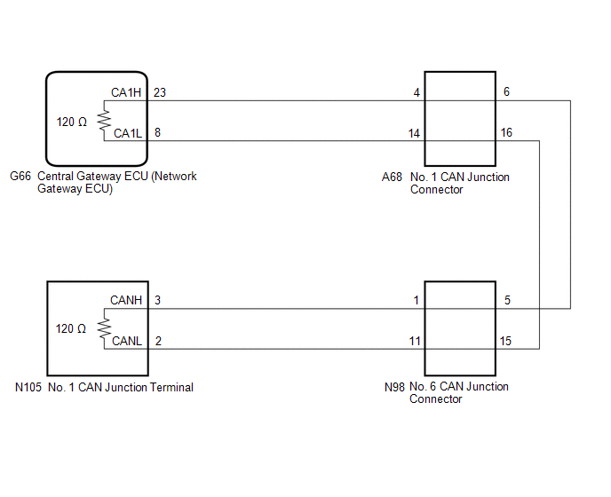
There may be an open circuit in one of the CAN main bus lines when the resistance between terminals 23 (CA1H) and 8 (CA1L) of the central gateway ECU (network gateway ECU) is 70 Ω or higher.
| Symptom | Trouble Area |
|---|---|
| Resistance between terminals 23 (CA1H) and 8 (CA1L) of the central gateway ECU (network gateway ECU) is 70 Ω or higher. |
|
This malfunction is not related to the lines of a CAN branch or to ECUs or sensors connected to a CAN branch.
WIRING DIAGRAM
CAUTION / NOTICE / HINT
CAUTION:
When performing the confirmation driving pattern, obey all speed limits and traffic laws.
NOTICE:
-
Because the order of diagnosis is important to allow correct diagnosis, make sure to begin troubleshooting using How to Proceed with Troubleshooting when CAN communication system related DTCs are output.
Click here
.gif)
- Before measuring the resistance of the CAN bus, turn the power switch off and leave the vehicle for 1 minute or more without operating the key or any switches, or opening or closing the doors. After that, disconnect the cable from the negative (-) auxiliary battery terminal and leave the vehicle for 1 minute or more before measuring the resistance.
-
After turning the power switch off, waiting time may be required before disconnecting the cable from the negative (-) auxiliary battery terminal. Therefore, make sure to read the disconnecting the cable from the negative (-) auxiliary battery terminal notices before proceeding with work.
Click here
-
After performing repairs, perform the DTC check procedure and confirm that the DTCs are not output again.
DTC check procedure: Turn the power switch on (IG) and wait for 1 minute or more. Then operate the suspected malfunctioning system and drive the vehicle at 60 km/h (37 mph) or more for 5 minutes or more.
-
After the repair, perform the CAN bus check and check that all the ECUs and sensors connected to the CAN communication system are displayed as normal.
Click here
HINT:
- Before disconnecting related connectors for inspection, push in on each connector body to check that the connector is not loose or disconnected.
- When a connector is disconnected, check that the terminals and connector body are not cracked, deformed or corroded.
PROCEDURE
| 1. | CHECK FOR OPEN IN CAN MAIN BUS LINES (NO. 1 CAN JUNCTION CONNECTOR) |
(a) Disconnect the cable from the negative (-) auxiliary battery terminal.
(b) Disconnect the A68 No. 1 CAN junction connector.
(c) Measure the resistance according to the value(s) in the table below.
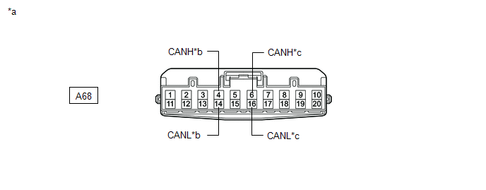
| *a | Front view of wire harness connector (to No. 1 CAN Junction Connector) | *b | to Central Gateway ECU (Network Gateway ECU) |
| *c | to No. 6 CAN Junction Connector | - | - |
Standard Resistance:
| Tester Connection | Condition | Specified Condition | Connected to |
|---|---|---|---|
| A68-4 (CANH) - A68-14 (CANL) | Cable disconnected from negative (-) auxiliary battery terminal | 108 to 132 Ω | Central gateway ECU (network gateway ECU) |
| A68-6 (CANH) - A68-16 (CANL) | Cable disconnected from negative (-) auxiliary battery terminal | 108 to 132 Ω | No. 6 CAN junction connector |
| Result | Proceed to |
|---|---|
| OK | A |
| NG (Line to central gateway ECU (network gateway ECU)) | B |
| NG (Line to No. 6 CAN junction connector) | C |
| A | .gif) | REPLACE NO. 1 CAN JUNCTION CONNECTOR |
| C | | GO TO STEP 3 |
|
.gif)
| 2. | CHECK FOR OPEN IN CAN MAIN BUS LINES (CENTRAL GATEWAY ECU (NETWORK GATEWAY ECU)) |
(a) Reconnect the A68 No. 1 CAN junction connector.
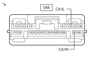
(b) Disconnect the G66 central gateway ECU (network gateway ECU) connector.
| (c) Measure the resistance according to the value(s) in the table below. Standard Resistance:
|
|
| OK | | REPLACE CENTRAL GATEWAY ECU (NETWORK GATEWAY ECU) |
| NG | | REPAIR OR REPLACE CAN MAIN BUS LINES OR CONNECTOR (CENTRAL GATEWAY ECU (NETWORK GATEWAY ECU) - NO. 1 CAN JUNCTION CONNECTOR) |
| 3. | CHECK FOR OPEN IN CAN MAIN BUS LINES (NO. 6 CAN JUNCTION CONNECTOR) |
(a) Reconnect the A68 No. 1 CAN junction connector.
(b) Disconnect the N98 No. 6 CAN junction connector.
(c) Measure the resistance according to the value(s) in the table below.
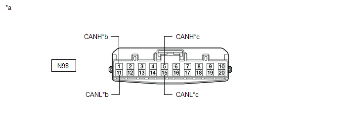
| *a | Front view of wire harness connector (to No. 6 CAN Junction Connector) | *b | to No. 1 CAN Junction Terminal |
| *c | to No. 1 CAN Junction Connector | - | - |
Standard Resistance:
| Tester Connection | Condition | Specified Condition | Connected to |
|---|---|---|---|
| N98-1 (CANH) - N98-11 (CANL) | Cable disconnected from negative (-) auxiliary battery terminal | 108 to 132 Ω | No. 1 CAN junction terminal |
| N98-5 (CANH) - N98-15 (CANL) | Cable disconnected from negative (-) auxiliary battery terminal | 108 to 132 Ω | No. 1 CAN junction connector |
| Result | Proceed to |
|---|---|
| OK | A |
| NG (Line to No. 1 CAN junction connector) | B |
| NG (Line to No. 1 CAN junction terminal) | C |
| A | | REPLACE NO. 6 CAN JUNCTION CONNECTOR |
| B | | REPAIR OR REPLACE CAN MAIN BUS LINES OR CONNECTOR (NO. 6 CAN JUNCTION CONNECTOR - NO. 1 CAN JUNCTION CONNECTOR) |
|
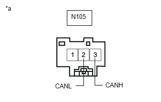
| 4. | CHECK FOR OPEN IN CAN MAIN BUS LINES (NO. 1 CAN JUNCTION TERMINAL) |
(a) Reconnect the N98 No. 6 CAN junction connector.
(b) Disconnect the N105 No. 1 CAN junction terminal connector.
| (c) Measure the resistance according to the value(s) in the table below. Standard Resistance:
|
|
| OK | | REPLACE NO. 1 CAN JUNCTION TERMINAL |
| NG | | REPAIR OR REPLACE CAN MAIN BUS LINES OR CONNECTOR (NO. 1 CAN JUNCTION TERMINAL - NO. 6 CAN JUNCTION CONNECTOR) |
READ NEXT:
 Grille Shutter Communication Stop Mode
DESCRIPTION Detection Item Symptom Trouble Area Grille Shutter Communication Stop Mode Any of the following conditions are met:
Communication stop for "Grill Shutter" is indicated on t
Restraints Occupant Classification System Module Communication Stop Mode
DESCRIPTION Detection Item Symptom Trouble Area Restraints Occupant Classification System Module Communication Stop Mode Any of the following conditions are met:
Communication stop for
Rear Television Camera Communication Stop Mode
DESCRIPTION Detection Item Symptom Trouble Area Rear Television Camera Communication Stop Mode Any of the following conditions are met:
Communication stop for "Parking Assist Monitor S
SEE MORE:
Switch Failure (B2342)
DESCRIPTION This DTC is stored when the sliding roof ECU (sliding roof drive gear sub-assembly) detects that the sliding roof switch (map light sub-assembly) is stuck for 30 seconds or more. DTC No. Detection Item DTC Detection Condition Trouble Area B2342 Switch Failure Sliding roo
Removal
REMOVAL CAUTION / NOTICE / HINT The necessary procedures (adjustment, calibration, initialization or registration) that must be performed after parts are removed and installed, or replaced during engine assembly removal/installation are shown below. Necessary Procedure After Parts Removed/Installed/
