Lexus ES: On-vehicle Inspection
ON-VEHICLE INSPECTION
CAUTION / NOTICE / HINT
CAUTION:
To prevent injury due to contact with an operating V-ribbed belt or cooling fan, keep your hands and clothing away from the V-ribbed belt and cooling fan when working in the engine compartment with the engine running or the ignition switch ON.
.png)
NOTICE:
This procedure includes the removal/installation of small-head bolts. Refer to Small-Head Bolts of Basic Repair Hint to identify the small-head bolts.
Click here .gif)
PROCEDURE
1. INSPECT ENGINE COOLANT
Click here
2. INSPECT ENGINE OIL
Click here
3. INSPECT BATTERY CONDITION
Click here
4. INSPECT SPARK PLUG
Click here
5. INSPECT AIR CLEANER FILTER ELEMENT SUB-ASSEMBLY
(a) Remove the air cleaner filter element sub-assembly.
(b) Visually check that the air cleaner filter element sub-assembly is not damaged or excessively oily. If necessary, replace the air cleaner filter element sub-assembly.
HINT:
- If there is any dirt or clogs in the air cleaner filter element sub-assembly, clean it with compressed air.
- If any dirt or clogs remain even after cleaning the air cleaner filter element sub-assembly with compressed air, replace it.
(c) Install the air cleaner filter element sub-assembly.
6. INSPECT V-RIBBED BELT
Click here
7. INSPECT V-RIBBED BELT TENSIONER ASSEMBLY
(a) Remove the V-ribbed belt.
Click here
(b) Turn the V-ribbed belt tensioner assembly clockwise and counterclockwise and check that it turns smoothly and does not catch.
HINT:
If the V-ribbed belt tensioner assembly does not turn smoothly or catches, replace the V-ribbed belt tensioner assembly.
(c) Install the V-ribbed belt.
Click here
8. INSPECT VALVE LASH ADJUSTER ASSEMBLY NOISE
(a) Rev up the engine several times. Check that the engine does not emit unusual noises.
(b) If unusual noises occur, warm up the engine and idle it for 30 minutes or more, then perform the inspection.
HINT:
If any defects or problems are found during the inspection, perform the valve lash adjuster assembly inspection.
Click here
9. INSPECT IGNITION TIMING
NOTICE:
- Check the ignition timing with the cooling fan off.
- Turn off all electrical systems and the A/C.
- When checking the ignition timing, the transaxle should be in park.
(a) Warm up and stop the engine.
(b) Connect the Techstream to the DLC3.
(c) Start the engine and run it at idle.
(d) Turn the Techstream on.
(e) Enter the following menus: Powertrain / Engine / Data List / Ignition Timing Cylinder #1.
Powertrain > Engine > Data List| Tester Display |
|---|
| Ignition Timing Cylinder #1 |
Standard Ignition Timing:
0 to 15° BTDC at idle
(f) Enter the following menus: Powertrain / Engine / Active Test / Activate the TC Terminal / ON.
Powertrain > Engine > Active Test| Active Test Display |
|---|
| Activate the TC Terminal |
| Data List Display |
|---|
| Ignition Timing Cylinder #1 |
(g) Monitor Ignition Timing Cylinder #1 of the Data List.
Standard Ignition Timing:
8 to 12° BTDC at idle
(h) Enter the following menus: Powertrain / Engine / Active Test / Activate the TC Terminal / OFF.
(i) Check that the ignition timing advances immediately when the engine speed is increased.
10. INSPECT ENGINE IDLE SPEED
NOTICE:
- Check the ignition timing with the cooling fan off.
- Turn off all electrical systems and the A/C.
- When checking the ignition timing, the transaxle should be in park.
(a) Warm up and stop the engine.
(b) Connect the Techstream to the DLC3.
(c) Start the engine and run it at idle.
(d) Turn the Techstream on.
(e) Enter the following menus: Powertrain / Engine / Data List / Engine Speed.
Powertrain > Engine > Data List| Tester Display |
|---|
| Engine Speed |
(f) Read the value displayed on the tester.
Standard Idle Speed:
600 to 700 rpm
11. INSPECT COMPRESSION
NOTICE:
Keep the spark plug holes free of foreign matter when measuring the compression pressure.
(a) Warm up and stop the engine.
(b) Check for DTCs.
Click here
(c) Remove the No. 1 engine cover sub-assembly.
Click here
(d) Remove the front wheel opening extension pad LH.
Click here
(e) Remove the front wheel opening extension pad RH.
Click here
(f) Remove the No. 1 engine under cover.
Click here
(g) Remove the No. 2 engine under cover assembly.
Click here
(h) Remove the 4 spark plugs.
Click here
| (i) Disconnect the fuel injector connector (for Port Injection). |
|
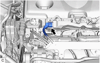
| (j) Disconnect the fuel injector connector (for Direct Injection). |
|
(k) Remove the air cleaner cap with air cleaner hose.
Click here
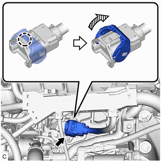
| (l) Using an 8 mm socket wrench, remove the 3 bolts to disconnect the throttle body with motor assembly from the intake manifold. |
|
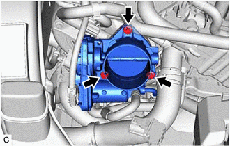
(m) Remove the throttle body gasket from the intake manifold.
Click here
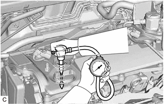
| (n) Check the cylinder compression pressure. (1) Insert a compression gauge into the spark plug hole. (2) While cranking the engine, measure the compression pressure. Standard Compression Pressure: 1500 kPa (15.3 kgf/cm2, 218 psi) Minimum Compression Pressure: 1300 kPa (13.3 kgf/cm2, 189 psi) Pressure Difference between Each Cylinder: 200 kPa (2.0 kgf/cm2, 29 psi) or less NOTICE:
(3) If the cylinder compression pressure is low, pour a small amount of engine oil into the cylinder through the spark plug hole and inspect it again. HINT:
|
|
(o) Install a new throttle body gasket to the intake manifold.
Click here
| (p) Using an 8 mm socket wrench, connect the throttle body with motor assembly to the intake manifold with the 3 bolts. Torque: 10 N·m {102 kgf·cm, 7 ft·lbf} |
|
(q) Install the air cleaner cap with air cleaner hose.
Click here
| (r) Connect the fuel injector connector (for Direct Injection). |
|
(s) Connect the fuel injector connector (for Port Injection).
(t) Install the 4 spark plugs.
Click here
(u) Install the No. 2 engine under cover assembly.
Click here
(v) Install the No. 1 engine under cover.
Click here
(w) Install the front wheel opening extension pad LH.
Click here
(x) Install the front wheel opening extension pad RH.
Click here
(y) Install the No. 1 engine cover sub-assembly.
Click here
(z) Clear the DTCs.
Click here
NOTICE:
After the inspection, clear the DTCs, check for DTCs again and make sure the normal system code is output.
12. INSPECT CO/HC
HINT:
This check determines whether or not the idle CO/HC complies with regulations.
(a) Start the engine.
(b) Run the engine at 2500 rpm for approximately 180 seconds.
(c) Insert a CO/HC meter testing probe at least 40 cm (1.31 ft.) into the tailpipe during idle.
(d) Immediately check the CO/HC concentration during idle and when the engine is running at 2500 rpm.
HINT:
When performing a 2 mode (with the engine idling/running at 2500 rpm) test, the measurement procedures are determined by applicable local regulations.
If the CO/HC concentration does not comply with the regulations, perform troubleshooting in the order given below.
(1) Check for DTCs.
Click here
(2) See the following table for possible causes, then inspect the applicable parts and repair them if necessary.
| CO | HC | Problem | Cause |
|---|---|---|---|
| Normal | High | Rough idle |
|
| Low | High | Rough idle (Fluctuating HC reading) |
|
| High | High | Rough idle (Black smoke from exhaust) |
|
READ NEXT:
 Precaution
PRECAUTION HINT:
Any digits beyond the 0.01 mm (1/1000 in.) place for standard, minimum and maximum values should be used as a reference only.
When both standard and maximum or minimum values are
Disassembly
DISASSEMBLY CAUTION / NOTICE / HINT NOTICE: This procedure includes the removal of small-head bolts. Refer to Small-Head Bolts of Basic Repair Hint to identify the small-head bolts. Click here PROCE
SEE MORE:
Evaporative Emission System Switching Valve Control Circuit Actuator Stuck Off (P24187F)
DTC SUMMARY DTC No. Detection Item DTC Detection Condition Trouble Area MIL Memory Note P24187F Evaporative Emission System Switching Valve Control Circuit Actuator Stuck Off Following condition met during key-off EVAP monitor:
EVAP pressure change when vent valve closed (o
Satellite Radio Broadcast cannot be Received
CAUTION / NOTICE / HINT NOTICE: Some satellite radio broadcasts require payment. A contract must be made between a satellite radio company and the user. If the contract expires, it will not be possible to listen to the broadcast. PROCEDURE 1. CHECK SURROUNDINGS (a) Check if the vehicle is i
