Lexus ES: On-vehicle Inspection
ON-VEHICLE INSPECTION
CAUTION / NOTICE / HINT
NOTICE:
If using a dropper to adjust the fluid amount, make sure that the dropper has not been used with mineral oils, water or deteriorated brake fluid. Sealed areas may deteriorate and lead to fluid leaks, or the fluid may deteriorate and lead to decreased efficiency.
HINT:
If the brake fluid level is lower than the MIN line, inspect for brake fluid leaks and brake pad wear. After repair or replacement, adjust the brake fluid level in the reservoir as specified below.
PROCEDURE
1. INSPECT AND ADJUST FLUID LEVEL IN RESERVOIR (When Using the Techstream)
(a) Connect the Techstream to the DLC3 with the power switch off.
(b) Check that the shift lever is in P and the parking brake is applied, and turn the power switch on (IG).
(c) Turn the Techstream on and enter the following menus: Chassis / ABS/VSC/TRAC / Utility / ECB (Electronically Controlled Brake system) Utility / Zero Down.
Chassis > ABS/VSC/TRAC > Utility| Tester Display |
|---|
| ECB Utility |
(d) Select "Next" and wait for 10 seconds.
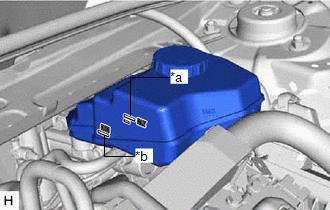
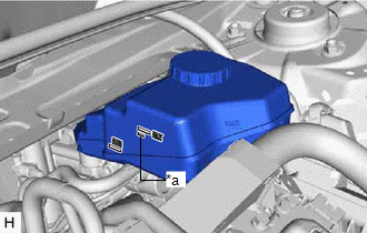
| (e) After the booster pump has stopped, check that the brake fluid level is between the MAX and MIN lines. If necessary, add brake fluid to the reservoir until the brake fluid level is at the MAX line. Brake Fluid: SAE J1703 or FMVSS No. 116 DOT3 SAE J1704 or FMVSS No. 116 DOT4 |
|
2. INSPECT AND ADJUST FLUID LEVEL IN RESERVOIR (When Not Using the Techstream)
| (a) Check that the fluid level is above the MIN line with the power switch on (IG). Adjust the brake fluid level of the reservoir so that it is between the MIN line and fluid level support line. Brake Fluid: SAE J1703 or FMVSS No. 116 DOT3 SAE J1704 or FMVSS No. 116 DOT4 |
|
READ NEXT:
 Replacement
REPLACEMENT CAUTION / NOTICE / HINT Click here
Precaution
PRECAUTION TROUBLESHOOTING PRECAUTION NOTICE:
Since the brake lines are critical safety related parts, be sure to disassemble and inspect the components if a brake fluid leak is found. If any abnor
SEE MORE:
Dtc Check / Clear
DTC CHECK / CLEAR CHECK DTC (a) Connect the Techstream to the DLC3. (b) Turn the engine switch on (IG). (c) Turn the Techstream on. (d) Enter the following menus: Body Electrical / Mirror L or Mirror R / Trouble Codes. Body Electrical > Mirror L > Trouble Codes Body Electrical > Mirror R &g
Inspection
INSPECTION PROCEDURE 1. INSPECT FRONT DOOR ILLUMINATION LIGHT LH (FRONT DOOR OUTSIDE HANDLE ASSEMBLY LH) *a Component without harness connected (Front Door Illumination Light LH (Front Door Outside Handle Assembly LH)) (a) Connect 4 dry-cell batteries (1.5 V) in series. NOTICE: Do not use r
