Lexus ES: Motor Electronics Coolant Pump "A" Component Internal Failure (P0C7396)
DTC SUMMARY
MALFUNCTION DESCRIPTION
This DTC is stored when the inverter water pump assembly is malfunctioning. The cause of this malfunction may be one of the following:
- Inverter water pump assembly internal malfunction
- Open or short in wire harness
- Improperly connected connector
- Foreign matter in inverter water pump assembly
- Hybrid cooling system coolant is frozen
HINT:
If this DTC is stored, the driving torque may be restricted.
DESCRIPTION
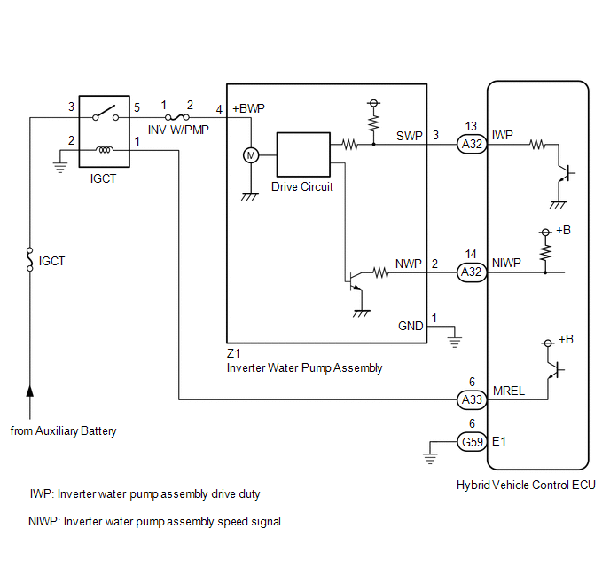
The inverter water pump assembly transmits rotation speed information to the hybrid vehicle control ECU. The hybrid vehicle control ECU monitors the speed and detects malfunctions.
| DTC No. | Detection Item | DTC Detection Condition | Trouble Area | MIL | Warning Indicate |
|---|---|---|---|---|---|
| P0C7396 | Motor Electronics Coolant Pump "A" Component Internal Failure | The inverter water pump assembly revolution speed is abnormally high or low (or stopped) for 1 minute or more. (1 trip detection logic) |
| Comes on | Master Warning Light: Comes on |
HINT:
The inverter water pump assembly operates when the power switch is on (READY).
Related Data List| DTC No. | Data List |
|---|---|
| P0C7396 |
|
| DTC No. | Active Test |
|---|---|
| P0C7396 | Activate the Inverter Water Pump |
MONITOR DESCRIPTION
The hybrid vehicle control ECU monitors speed of the inverter water pump assembly. If there is an abnormality in speed, the hybrid vehicle control ECU will illuminate the MIL and store a DTC.
MONITOR STRATEGY
| Related DTCs | P0C73 (INF P0C7396): Motor Electronics Coolant Pump "A" malfunction |
| Required sensors/components | Inverter water pump assembly |
| Frequency of operation | Continuous |
| Duration | TMC's intellectual property |
| MIL operation | 1 driving cycle |
| Sequence of operation | None |
TYPICAL ENABLING CONDITIONS
| The monitor will run whenever the following DTCs are not stored | TMC's intellectual property |
| Other conditions belong to TMC's intellectual property | - |
TYPICAL MALFUNCTION THRESHOLDS
| TMC's intellectual property | - |
COMPONENT OPERATING RANGE
| Hybrid vehicle control ECU | DTC P0C73 (INF P0C7396) is not detected |
CONFIRMATION DRIVING PATTERN
HINT:
-
After repair has been completed, clear the DTC and then check that the vehicle has returned to normal by performing the following All Readiness check procedure.
Click here
.gif)
-
When clearing the permanent DTCs, refer to the "CLEAR PERMANENT DTC" procedure.
Click here
- Connect the Techstream to the DLC3.
- Turn the power switch on (IG) and turn the Techstream on.
- Clear the DTCs (even if no DTCs are stored, perform the clear DTC procedure).
- Turn the power switch off and wait for 2 minutes or more.
- Turn the power switch on (IG) and turn the Techstream on.
- Turn the power switch on (READY). [*1]
-
Wait for 2 minutes or more. [*2]
HINT:
[*1] to [*2] : Normal judgment procedure.
The normal judgment procedure is used to complete DTC judgment and also used when clearing permanent DTCs.
- Enter the following menus: Powertrain / Hybrid Control / Utility / All Readiness.
-
Check the DTC judgment result.
HINT:
- If the judgment result shows NORMAL, the system is normal.
- If the judgment result shows ABNORMAL, the system has a malfunction.
- If the judgment result shows INCOMPLETE or N/A, perform the normal judgment procedure again.
WIRING DIAGRAM
CAUTION / NOTICE / HINT
NOTICE:
If this vehicle is jump started, etc. and excessive voltage is applied to the auxiliary battery, the inverter water pump assembly may suspend control as a self-protection function and store DTCs.
(When the auxiliary battery voltage returns to normal, the inverter water pump assembly will resume normal operation. In this case it is not necessary to replace the inverter water pump assembly.)
PROCEDURE
| 1. | CHECK DTC OUTPUT (HYBRID CONTROL) |
(a) Connect the Techstream to the DLC3.
(b) Turn the power switch on (IG).
(c) Enter the following menus: Powertrain / Hybrid Control / Trouble Codes.
(d) Check for DTCs.
Powertrain > Hybrid Control > Trouble Codes| Result | Proceed to |
|---|---|
| P0C7396 only is output, or DTCs except the ones in the table below are also output. | A |
| Any of the following DTCs including pending DTCs are also output. | B |
| Malfunction Content | Relevant DTC | |
|---|---|---|
| Microcomputer malfunction | P060647 | Hybrid/EV Powertrain Control Module Processor Watchdog / Safety MCU Failure |
| P06881F | ECM/PCM Power Relay Sense Circuit Intermittent | |
| Sensor and actuator circuit malfunction | P314A31 | Motor Electronics Coolant Pump "A" No Signal |
HINT:
P0C7396 may be output as a result of the malfunction indicated by the DTCs above.
- The chart above is listed in inspection order of priority.
- Check DTCs that are output at the same time by following the listed order. (The main cause of the malfunction can be determined without performing unnecessary inspections.)
(e) Turn the power switch off.
| B | .gif) | GO TO DTC CHART (HYBRID CONTROL SYSTEM) |
|
.gif)
| 2. | READ VALUE USING TECHSTREAM (INVERTER WATER PUMP REVOLUTION) |
NOTICE:
Be sure to perform the inspection with the auxiliary battery voltage at 12 V or more.
HINT:
- When the auxiliary battery voltage is low, the inverter water pump assembly may not operate.
- When the inverter water pump assembly signal line (SWP - IWP) is open or its connection is faulty, the inverter water pump assembly is operated forcibly.
(a) Connect the Techstream to the DLC3.
(b) Turn the power switch on (IG).
(c) Enter the following menus: Powertrain / Hybrid Control / Data List / Inverter Water Pump Revolution.
Powertrain > Hybrid Control > Data List| Tester Display |
|---|
| Inverter Water Pump Revolution |
(d) According to the display on the Techstream, read the Data List.
OK:
| Tester Display | Condition | Specified Condition |
|---|---|---|
| Inverter Water Pump Revolution | Power switch on (IG) | 200 rpm or less |
HINT:
When the inverter water pump assembly is not operating, the Data List item "Inverter Water Pump Revolution" displays a value 200 rpm or less.
(e) Turn the power switch off.
| NG | | GO TO STEP 6 |
|
| 3. | CLEAR DTC |
Click here
|
| 4. | PERFORM ACTIVE TEST USING TECHSTREAM (ACTIVATE THE INVERTER WATER PUMP) |
NOTICE:
- Make sure that the HV coolant level is above the low line of the inverter reserve tank.
- Be sure to perform the inspection with the auxiliary battery voltage at 12 V or more.
HINT:
When the auxiliary battery voltage is low, the inverter water pump assembly may not operate.
(a) Connect the Techstream to the DLC3.
(b) Turn the power switch on (IG).
(c) Enter the following menus: Powertrain / Hybrid Control / Active Test / Activate the Inverter Water Pump.
(d) Select the Data List item "Inverter Water Pump Revolution".
Powertrain > Hybrid Control > Active Test| Active Test Display |
|---|
| Activate the Inverter Water Pump |
| Data List Display |
|---|
| Inverter Water Pump Revolution |
(e) According to the display on the Techstream, perform the Active Test "Activate the Inverter Water Pump" and, check the value of the Data List item "Inverter Water Pump Revolution".
OK:
| Tester Display | Condition | Specified Condition |
|---|---|---|
| Inverter Water Pump Revolution | Power switch on (IG) During Active Test | 3176 to 8617 rpm |
HINT:
- Perform the Active Test with the inverter coolant temperature between -15 and 65°C (5 to 149°F).
- When the inverter water pump assembly is not operating, the Data List item "Inverter Water Pump Revolution" displays a value 200 rpm or less.
(f) Turn the power switch off.
| NG | | GO TO STEP 6 |
|
| 5. | CHECK HV COOLANT (CHECK FOR CONDITIONS THAT MAY HAVE CAUSED FREEZING) |
Click here
| Result | Proceed to |
|---|---|
| Ambient Temperature value is above freezing temperature of the HV coolant. | A |
| Ambient Temperature value is below freezing temperature of the HV coolant. | B |
| A | | GO TO STEP 12 |
| B | | REPLACE HV COOLANT |
| 6. | CHECK CONNECTOR CONNECTION CONDITION (HYBRID VEHICLE CONTROL ECU CONNECTOR) |
Click here
| NG | | CONNECT SECURELY |
|
| 7. | CHECK CONNECTOR CONNECTION CONDITION (INVERTER WATER PUMP ASSEMBLY CONNECTOR) |
Click here
| NG | | CONNECT SECURELY |
|
| 8. | CHECK HARNESS AND CONNECTOR (HYBRID VEHICLE CONTROL ECU - INVERTER WATER PUMP ASSEMBLY) |
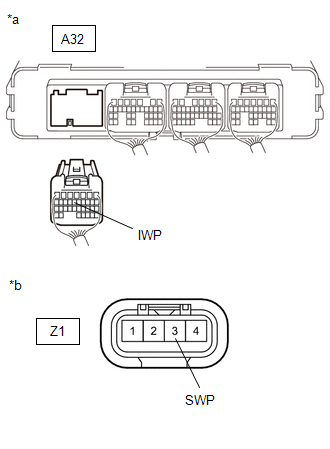
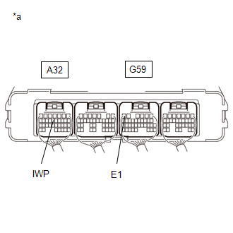
(a) Disconnect the A32 hybrid vehicle control ECU connector.
(b) Disconnect the Z1 inverter water pump assembly connector.
| (c) Measure the resistance according to the value(s) in the table below. Standard Resistance (Check for Open):
Standard Resistance (Check for Short):
HINT: Check the condition (looseness, deterioration, etc.) of the wire to body ground for the inverter water pump assembly. |
|
(d) Reconnect the Z1 inverter water pump assembly connector.
(e) Reconnect the A32 hybrid vehicle control ECU connector.
| NG | | REPAIR OR REPLACE HARNESS OR CONNECTOR |
|
| 9. | READ VALUE USING TECHSTREAM (INVERTER WATER PUMP REVOLUTION) |
NOTICE:
Be sure to perform the inspection with the auxiliary battery voltage at 12 V or more.
HINT:
When the auxiliary battery voltage is low, the inverter water pump assembly may not operate.
(a) Connect the Techstream to the DLC3.
| (b) Remove the INV W/PMP fuse from No. 4 relay block. |
|
(c) Turn the power switch on (IG).
(d) Enter the following menus: Powertrain / Hybrid Control / Data List / Inverter Water Pump Revolution.
Powertrain > Hybrid Control > Data List| Tester Display |
|---|
| Inverter Water Pump Revolution |
(e) According to the display on the Techstream, read the Data List.
OK:
| Tester Display | Condition | Specified Condition |
|---|---|---|
| Inverter Water Pump Revolution | Power switch on (IG) | 200 rpm or less |
(f) Turn the power switch off.
(g) Install the INV W/PMP fuse.
| NG | | REPLACE HYBRID VEHICLE CONTROL ECU |
|
| 10. | CHECK HARNESS AND CONNECTOR (HYBRID VEHICLE CONTROL ECU - INVERTER WATER PUMP ASSEMBLY) |
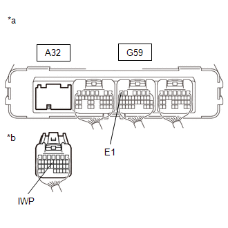
(a) Disconnect the A32 hybrid vehicle control ECU connector.
(b) Turn the power switch on (IG).
| (c) Measure the voltage according to the value(s) in the table below. Standard Voltage:
NOTICE: Turning the power switch on (IG) with the hybrid vehicle control ECU connector disconnected causes other DTCs to be stored. Clear the DTCs after performing this inspection. |
|
(d) Turn the power switch off.
(e) Reconnect the A32 hybrid vehicle control ECU connector.
| NG | | GO TO STEP 12 |
|
| 11. | CHECK HYBRID VEHICLE CONTROL ECU (CHECK WAVEFORM) |
(a) Connect an oscilloscope between the hybrid vehicle control ECU terminals specified in the table below.
| (b) Check the waveform while turning the power switch on (IG).
OK: Waveform duty ratio is between 3% and 9%. |
|
(c) Turn the power switch off.
| NG | | REPLACE HYBRID VEHICLE CONTROL ECU |
|
| 12. | REPLACE INVERTER WATER PUMP ASSEMBLY |
Click here
|
| 13. | ADD HV COOLANT AND PERFORM AIR BLEEDING |
(a) After replacing the inverter water pump assembly, add HV coolant and perform air bleeding.
Click here
| NEXT | | END |
READ NEXT:
 Hybrid/EV Battery System Discharge Time Too Long (P0C7600)
DTC SUMMARY MALFUNCTION DESCRIPTION When the power switch is turned from on (READY) to off, the hybrid vehicle control ECU detect that the high-voltage capacitor inside the inverter with converter ass
Drive Motor "A" Inverter Voltage Sensor Voltage Out of Range (P0D2D1C)
DTC SUMMARY MALFUNCTION DESCRIPTION The hybrid vehicle control ECU detects a VH sensor malfunction. The cause of this malfunction may be one of the following: Inverter voltage sensor internal circuit
Boosting Converter Voltage Sensor "A" Voltage Out of Range (P0E311C)
DTC SUMMARY MALFUNCTION DESCRIPTION The hybrid vehicle control ECU detects a VL sensor malfunction. The cause of this malfunction may be one of the following: Inverter voltage (VL) sensor internal ci
SEE MORE:
Rear Height Control Sensor (B241A)
DESCRIPTION The headlight ECU sub-assembly LH determines the vehicle height and performs automatic headlight beam level control based on signals from the rear height control sensor sub-assembly LH via direct line. DTC No. Detection Item DTC Detection Condition Trouble Area DTC Output from
Components
COMPONENTS ILLUSTRATION *A w/ Stud Bolt *B w/o Stud Bolt *1 INTAKE MANIFOLD *2 NO. 1 INTAKE MANIFOLD TO HEAD GASKET *3 NO. 1 ENGINE COVER *4 VACUUM HOSE *5 NO. 2 FUEL VAPOR FEED HOSE *6 NO. 2 WATER BY-PASS PIPE *7 NO. 3 WATER BY-PASS PIPE *8 ENGINE W
