Lexus ES: Manifold Absolute Pressure / Barometric Pressure Sensor Circuit Short to Ground (P010511)
DESCRIPTION
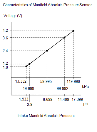
The manifold absolute pressure sensor detects the intake manifold pressure as a change in voltage. The ECM calculates the intake manifold pressure based on this voltage. The ECM calculates the EGR valve assembly and purge VSV opening amount according to changes in the intake manifold pressure and also detects malfunctions of the manifold absolute pressure sensor using these changes in pressure.
| DTC No. | Detection Item | DTC Detection Condition | Trouble Area | MIL | Memory | Note |
|---|---|---|---|---|---|---|
| P010511 | Manifold Absolute Pressure / Barometric Pressure Sensor Circuit Short to Ground | The manifold absolute pressure sensor output voltage is less than 0.5 V for 0.5 seconds or more (1 trip detection logic). |
| Comes on | DTC stored | SAE Code: P0107 |
HINT:
When this DTC is output, check the intake manifold absolute pressure in the Data List. Enter the following menus: Powertrain / Engine / Data List / Intake Manifold Absolute Pressure.
| DTC No. | Intake Manifold Absolute Pressure | Malfunction |
|---|---|---|
| P010511 | Approximately 0 kPa (0 psi) |
|
If the Data List value is normal it may be due to a temporary recovery from the malfunction condition. Check for intermittent problems.
Click here .gif)
MONITOR DESCRIPTION
The ECM monitors the manifold absolute pressure sensor voltage and uses this value to calculate the intake manifold pressure. When the manifold absolute pressure sensor output voltage deviates from the normal operating range, the ECM interprets this as a malfunction in the manifold absolute pressure sensor circuit, illuminates the MIL and stores a DTC.
Example:
If the manifold absolute pressure sensor output voltage is less than 0.5 V for 0.5 seconds or more, the ECM stores this DTC.
MONITOR STRATEGY
| Related DTCs | P0107: Manifold absolute pressure sensor range check (low voltage) |
| Required Sensors/Components (Main) | Manifold absolute pressure sensor |
| Required Sensors/Components (Related) | - |
| Frequency of Operation | Continuous |
| Duration | 0.5 seconds |
| MIL Operation | Immediate |
| Sequence of Operation | None |
TYPICAL ENABLING CONDITIONS
| Monitor runs whenever the following DTCs are not stored | None |
| All of the following conditions are met | - |
| Auxiliary battery voltage | 8 V or higher |
| Power switch | On (IG) |
| Time after power switch off to on (IG) | 0.5 seconds or more |
| Time after starter on to off | More than 2 seconds |
TYPICAL MALFUNCTION THRESHOLDS
| Manifold absolute pressure sensor voltage (Manifold absolute pressure) | Less than 0.5 V (Less than 0 kPa(abs) [0 psi(abs)]) |
CONFIRMATION DRIVING PATTERN
HINT:
-
After repair has been completed, clear the DTC and then check that the vehicle has returned to normal by performing the following All Readiness check procedure.
Click here
-
When clearing the permanent DTCs, refer to the "CLEAR PERMANENT DTC" procedure.
Click here
- Connect the Techstream to the DLC3.
- Turn the power switch on (IG).
- Turn the Techstream on.
- Clear the DTCs (even if no DTCs are stored, perform the clear DTC procedure).
- Turn the power switch off and wait for at least 30 seconds.
- Turn the power switch on (IG).
- Turn the Techstream on.
-
Put the engine in Inspection Mode (Maintenance Mode).
Click here
- Start the engine and wait 5 seconds or more [A].
- Enter the following menus: Powertrain / Engine / Trouble Codes [B].
-
Read the pending DTCs.
HINT:
- If a pending DTC is output, the system is malfunctioning.
- If a pending DTC is not output, perform the following procedure.
- Enter the following menus: Powertrain / Engine / Utility / All Readiness.
- Input the DTC: P010511.
-
Check the DTC judgment result.
Techstream Display
Description
NORMAL
- DTC judgment completed
- System normal
ABNORMAL
- DTC judgment completed
- System abnormal
INCOMPLETE
- DTC judgment not completed
- Perform driving pattern after confirming DTC enabling conditions
HINT:
- If the judgment result is NORMAL, the system is normal.
- If the judgment result is ABNORMAL, the system is malfunctioning.
-
[A] to [B]: Normal judgment procedure.
The normal judgment procedure is used to complete DTC judgment and also used when clearing permanent DTCs.
- When clearing the permanent DTCs, do not disconnect the cable from the auxiliary battery terminal or attempt to clear the DTCs during this procedure, as doing so will clear the universal trip and normal judgment histories.
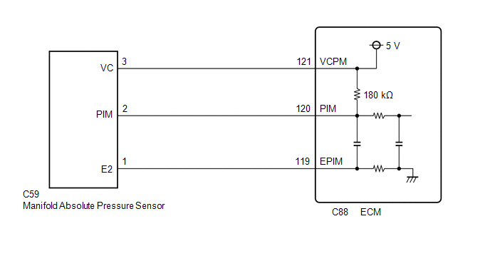
WIRING DIAGRAM
CAUTION / NOTICE / HINT
NOTICE:
-
Vehicle Control History may be stored in the hybrid vehicle control ECU assembly if the engine is malfunctioning. Certain vehicle condition information is recorded when Vehicle Control History is stored. Reading the vehicle conditions recorded in both the Freeze Frame Data and Vehicle Control History can be useful for troubleshooting.
Click here
(Select Powertrain in Health Check and then check the time stamp data.)
Click here
-
If any "Engine Malfunction" Vehicle Control History item has been stored in the hybrid vehicle control ECU assembly, make sure to clear it. However, as all Vehicle Control History items are cleared simultaneously, if any Vehicle Control History items other than "Engine Malfunction" are stored, make sure to perform any troubleshooting for them before clearing Vehicle Control History.
Click here
HINT:
Read Freeze Frame Data using the Techstream. The ECM records vehicle and driving condition information as Freeze Frame Data the moment a DTC is stored. When troubleshooting, Freeze Frame Data can help determine if the vehicle was moving or stationary, if the engine was warmed up or not, if the air fuel ratio was lean or rich, and other data from the time the malfunction occurred.
PROCEDURE
| 1. | CHECK HARNESS AND CONNECTOR |
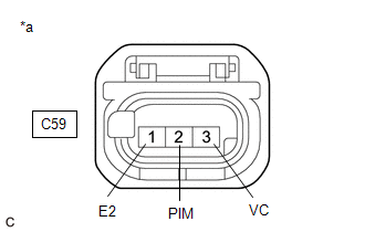
| *a | Front view of wire harness connector (to Manifold Absolute Pressure Sensor) |
HINT:
Make sure that the connector is properly connected. If it is not, securely connect it and check for DTCs again.
(a) Disconnect the manifold absolute pressure sensor connector.
(b) Turn the power switch on (IG).
(c) Measure the voltage according to the value(s) in the table below.
Standard Voltage:
| Tester Connection | Condition | Specified Condition |
|---|---|---|
| C59-3 (VC) - C59-1 (E2) | Power switch on (IG) | 4.75 to 5.25 V |
| C59-2 (PIM) - C59-1 (E2) | Power switch on (IG) | 1.2 to 5.25 V |
(d) Turn the power switch off and wait for at least 30 seconds.
(e) Measure the resistance according to the value(s) in the table below.
Standard Resistance:
| Tester Connection | Condition | Specified Condition |
|---|---|---|
| C59-3 (VC) - C59-2 (PIM) | Power switch off | 171 to 189 kΩ |
| OK | .gif) | REPLACE MANIFOLD ABSOLUTE PRESSURE SENSOR |
|
.gif)
| 2. | CHECK HARNESS AND CONNECTOR (MANIFOLD ABSOLUTE PRESSURE SENSOR - ECM) |
(a) Disconnect the manifold absolute pressure sensor connector.
(b) Disconnect the ECM connector.
(c) Measure the resistance according to the value(s) in the table below.
Standard Resistance:
| Tester Connection | Condition | Specified Condition |
|---|---|---|
| C59-3 (VC) - C88-121 (VCPM) | Always | Below 1 Ω |
| C59-2 (PIM) or C88-120 (PIM) - Body ground and other terminals | Always | 10 kΩ or higher |
| OK | | REPLACE ECM |
| NG | | REPAIR OR REPLACE HARNESS OR CONNECTOR |
READ NEXT:
 Manifold Absolute Pressure / Barometric Pressure Sensor Circuit Short to Battery or Open (P010515)
DESCRIPTION Refer to DTC P010511. Click here DTC No. Detection Item DTC Detection Condition Trouble Area MIL Memory Note P010515 Manifold Absolute Pressure / Barometric Pressure
Manifold Absolute Pressure / Barometric Pressure Sensor Signal Stuck in Range (P01052A)
DESCRIPTION Refer to DTC P010511. Click here DTC No. Detection Item DTC Detection Condition Trouble Area MIL Memory Note P01052A Manifold Absolute Pressure / Barometric Pressure
Intake Air Temperature Sensor 1 Bank 1 Circuit Short to Ground (P011011)
DESCRIPTION The intake air temperature sensor, mounted on the mass air flow meter sub-assembly, monitors the intake air temperature. The intake air temperature sensor has a built-in thermistor with a
SEE MORE:
Fail-safe Chart
FAIL-SAFE CHART FAIL-SAFE FUNCTION (a) When a malfunction occurs in the tire pressure warning system, the tire pressure warning light illuminates after blinking for 1 minute to inform the driver of the system failure. (b) As a result of this, tire pressure monitoring is disabled and a DTC is stored
Components
COMPONENTS ILLUSTRATION *A w/ Power Trunk Lid System - - *1 LUGGAGE COMPARTMENT DOOR COVER *2 LUGGAGE LOCK CONTROL CABLE PLATE *3 SWITCH BEZEL - - ILLUSTRATION *1 REAR LIGHT ASSEMBLY *2 REAR LIGHT GASKET *3 REAR LIGHT PROTECTOR - - N*m (kgf
