Lexus ES: Luggage Compartment Door Opener Outer Switch
Components
COMPONENTS
ILLUSTRATION
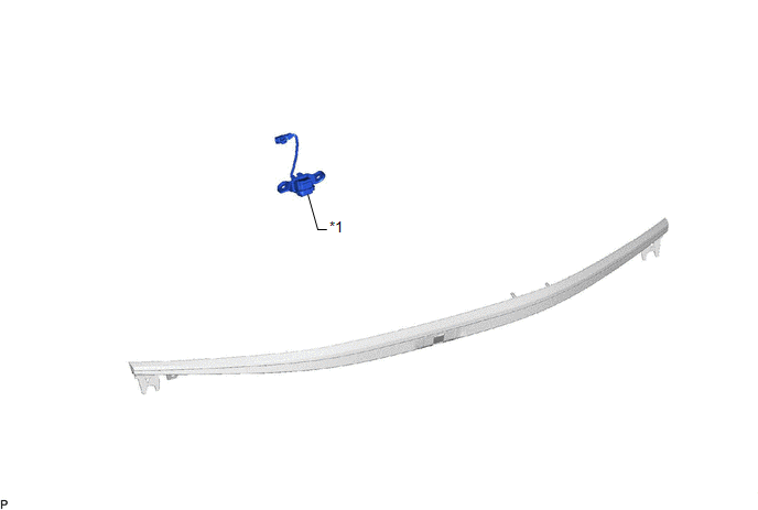
| *1 | LUGGAGE ELECTRICAL KEY SWITCH | - | - |
Removal
REMOVAL
PROCEDURE
1. REMOVE LUGGAGE COMPARTMENT DOOR OUTSIDE GARNISH SUB-ASSEMBLY
Click here .gif)
2. REMOVE LUGGAGE ELECTRICAL KEY SWITCH
| (a) Disconnect the connector. |
|
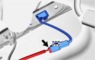
(b) Disengage the clamp.
(c) Disengage the claw and remove the luggage electrical key switch.

.png) | Remove in this Direction |
Inspection
INSPECTION
PROCEDURE
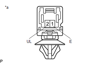
1. INSPECT LUGGAGE ELECTRICAL KEY SWITCH
(a) Check the switch.
| (1) Measure the resistance according to the value(s) in the table below. Standard Resistance:
If the result is not as specified, replace the luggage electrical key switch. |
|
Installation
INSTALLATION
PROCEDURE
1. INSTALL LUGGAGE ELECTRICAL KEY SWITCH
(a) Engage the claw to install the luggage electrical key switch.
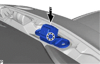
.png) | Install in this Direction |
(b) Engage the clamp.
(c) Connect the connector.
2. INSTALL LUGGAGE COMPARTMENT DOOR OUTSIDE GARNISH SUB-ASSEMBLY
Click here .gif)
READ NEXT:
 Precaution
PRECAUTION PRECAUTION FOR DISCONNECTING CABLE FROM NEGATIVE BATTERY TERMINAL NOTICE: When disconnecting the cable from the negative (-) battery terminal, initialize the following systems after the cab
Parts Location
PARTS LOCATION ILLUSTRATION *1 TRUNK AND FUEL SWITCH ASSEMBLY *2 LUGGAGE DOOR OPENING CANCEL SWITCH ASSEMBLY *3 DLC3 *4 MAIN BODY ECU (MULTIPLEX NETWORK BODY ECU) *5 INSTRUME
SEE MORE:
Data List / Active Test
DATA LIST / ACTIVE TEST DATA LIST NOTICE: In the table below, the values listed under "Normal Condition" are reference values. Do not depend solely on these reference values when deciding whether a part is faulty or not. HINT: Using the Techstream to read the Data List allows the values or states of
Inspection
INSPECTION PROCEDURE 1. INSPECT STEERING COLUMN ASSEMBLY (a) Check that the 2 bushings are securely installed to the steering column assembly. HINT: If the bushings are deformed, missing or damaged, replace the steering column assembly with a new one.
