Lexus ES: Lost Communication with Battery Monitor Module Missing Message (P162B87)
DESCRIPTION
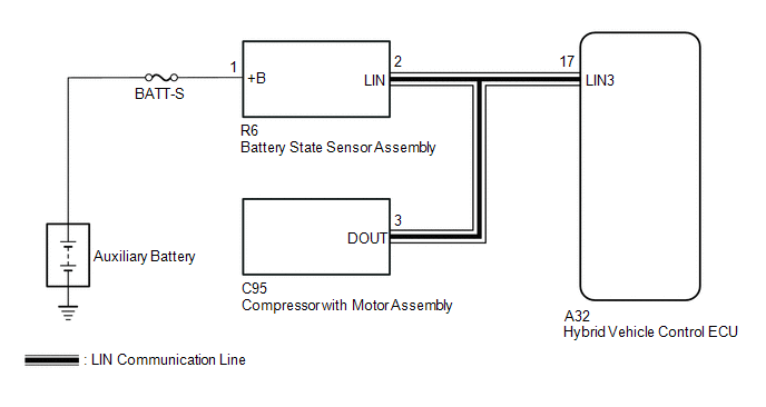
The hybrid vehicle control ECU communicates with the battery state sensor assembly via LIN communication. If a LIN communication error is detected, the hybrid vehicle control ECU stores this DTC.
| DTC No. | Detection Item | DTC Detection Condition | Trouble Area | Warning Indicate | Memory |
|---|---|---|---|---|---|
| P162B87 | Lost Communication with Battery Monitor Module Missing Message | Battery state sensor assembly or hybrid vehicle control ECU communication stops for approximately 17 minutes or more with the power switch on (IG). (1 trip detection logic) |
| Charge warning is not displayed | DTC stored |
WIRING DIAGRAM
CAUTION / NOTICE / HINT
NOTICE:
- Inspect the fuses for circuits related to this system before performing the following procedure.
-
Make sure to perform the necessary procedures (adjustment, calibration, initialization, or registration) after parts related to the charging system have been removed/installed or replaced.
Click here
.gif)
PROCEDURE
| 1. | CHECK BATTERY STATE SENSOR ASSEMBLY |
(a) Check installation condition of the battery state sensor assembly.
| NG | .gif) | INSTALL THE BATTERY STATE SENSOR ASSEMBLY CORRECTLY |
|
.gif)
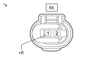
| 2. | CHECK HARNESS AND CONNECTOR (POWER SOURCE CIRCUIT) |
(a) Check that the battery state sensor assembly connector is securely connected.
OK:
The connector is securely connected.
(b) Disconnect the R6 battery state sensor assembly connector.
(c) Check the connector case and terminals for deformation or corrosion.
OK:
No deformation or corrosion.
| (d) Measure the voltage according to the value(s) in the table below. Standard Voltage:
|
|
| NG | | REPAIR OR REPLACE HARNESS OR CONNECTOR (AUXILIARY BATTERY - BATTERY STATE SENSOR ASSEMBLY) |
|
| 3. | CHECK HARNESS AND CONNECTOR (HYBRID VEHICLE CONTROL ECU - BATTERY STATE SENSOR ASSEMBLY) |
(a) Disconnect the A32 hybrid vehicle control ECU connector.
(b) Disconnect the R6 battery state sensor assembly connector.
(c) Disconnect the C95 compressor with motor assembly connector.
(d) Measure the resistance according to the value(s) in the table below.
Standard Resistance:
| Tester Connection | Condition | Specified Condition |
|---|---|---|
| A32-17 (LIN3) - R6-2 (LIN) | Always | Below 1 Ω |
| R6-2 (LIN), A32-17 (LIN3) or C95-3 (DOUT) - Body ground | Always | 10 kΩ or higher |
| NG | | REPAIR OR REPLACE HARNESS OR CONNECTOR |
|
| 4. | CLEAR DTCS |
(a) Connect the Techstream to the DLC3.
(b) Turn the power switch on (IG).
(c) Turn the Techstream on.
(d) Enter the following menus: Powertrain / Hybrid Control / Trouble Codes.
(e) Check for DTCs, and note down any DTCs that are output.
Powertrain > Hybrid Control > Trouble Codes(f) Enter the following menus: Powertrain / Hybrid Control / Trouble Codes.
(g) Clear the DTCs.
Powertrain > Hybrid Control > Clear DTCs(h) Turn the power switch off and wait for at least 30 seconds or more.
|
| 5. | CLEAR DTCS (AIR CONDITIONING SYSTEM) |
(a) Enter the following menus: Body Electrical / Air Conditioner / Trouble Codes.
(b) Check for DTCs, and note down any DTCs that are output.
Body Electrical > Air Conditioner > Trouble Codes(c) Enter the following menus: Body Electrical / Air Conditioner / Trouble Codes.
(d) Clear the DTCs.
Body Electrical > Air Conditioner > Clear DTCs(e) Turn the power switch off and wait for at least 30 seconds or more.
|
| 6. | CHECK FOR DTCS |
(a) Turn the power switch on (READY) and wait for 17 minutes or more.
(b) Enter the following menus: Powertrain / Hybrid Control / Trouble Codes.
(c) Check for DTCs.
Powertrain > Hybrid Control > Trouble Codes| Result | Proceed to |
|---|---|
| DTC P162B87 is output. | A |
| DTCs are not output. | B |
| B | | CHECK FOR INTERMITTENT PROBLEMS |
|
| 7. | CHECK FOR DTCS (AIR CONDITIONING SYSTEM) |
(a) Connect the Techstream to the DLC3.
(b) Turn the power switch on (IG).
(c) Turn the Techstream on.
(d) Enter the following menus: Body Electrical / Air Conditioner / Trouble Codes.
(e) Check for DTCs when the following conditions are met.
Body Electrical > Air Conditioner > Trouble Codes| Result | Proceed to |
|---|---|
| DTC B1498 is output. | A |
| DTCs are not output. | B |
| A | | REPLACE HYBRID VEHICLE CONTROL ECU |
| B | | REPLACE BATTERY STATE SENSOR ASSEMBLY |
READ NEXT:
 Lost Communication with Battery Monitor Module Missing Message (P162B87)
DESCRIPTION The hybrid vehicle control ECU communicates with the battery state sensor assembly via LIN communication. If a LIN communication error is detected, the hybrid vehicle control ECU stores th
Auxiliary Battery Monitor Module Range/Performance (P058A01)
DESCRIPTION The battery state sensor assembly detects the auxiliary voltage, current and temperature of the auxiliary battery. The battery state sensor assembly calculates State of Charge (SOC) based
On-vehicle Inspection
ON-VEHICLE INSPECTION PROCEDURE 1. CHECK AUXILIARY BATTERY (a) Check that the auxiliary battery cables are connected to the correct terminals. If they are not, connect them properly. (b) Check the aux
SEE MORE:
Terminals Of Ecu
TERMINALS OF ECU CHECK MULTIPLEX NETWORK MASTER SWITCH ASSEMBLY (a) Disconnect the J20 multiplex network master switch assembly connector. (b) Measure the voltage and resistance according to the value(s) in the table below. HINT: Measure the values on the wire harness side with the connector discon
If the electronic key does not
operate properly
If communication between the
electronic key and vehicle is interrupted or the electronic
key cannot be used because the
battery is depleted, the smart
access system with push-button
start and wireless remote control
cannot be used. In such cases, the
doors and trunk can be opened and
the hyb
