Lexus ES: Rear Television Camera Communication Stop Mode
DESCRIPTION
| Detection Item | Symptom | Trouble Area |
|---|---|---|
| Rear Television Camera Communication Stop Mode | Any of the following conditions are met:
|
|
WIRING DIAGRAM
w/ Panoramic View Monitor System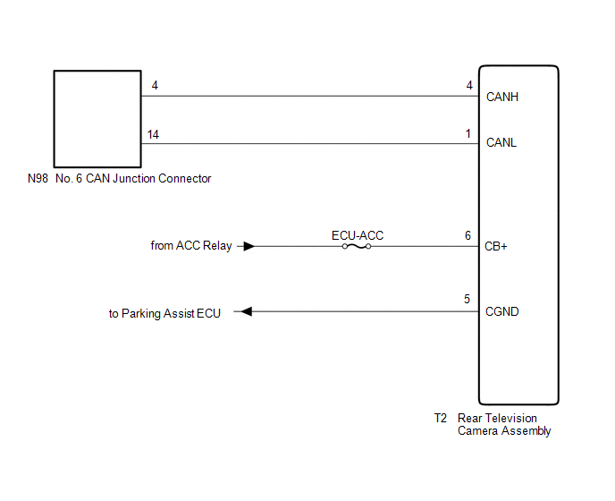 w/o Panoramic View Monitor System
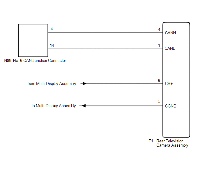
CAUTION / NOTICE / HINT
CAUTION:
When performing the confirmation driving pattern, obey all speed limits and traffic laws.
NOTICE:
-
Because the order of diagnosis is important to allow correct diagnosis, make sure to begin troubleshooting using How to Proceed with Troubleshooting when CAN communication system related DTCs are output.
Click here
.gif)
- Before measuring the resistance of the CAN bus, turn the engine switch off and leave the vehicle for 1 minute or more without operating the key or any switches, or opening or closing the doors. After that, disconnect the cable from the negative (-) battery terminal and leave the vehicle for 1 minute or more before measuring the resistance.
-
After turning the engine switch off, waiting time may be required before disconnecting the cable from the negative (-) battery terminal. Therefore, make sure to read the disconnecting the cable from the negative (-) battery terminal notices before proceeding with work.
Click here
-
After performing repairs, perform the DTC check procedure and confirm that the DTCs are not output again.
DTC check procedure: Turn the engine switch on (IG) and wait for 1 minute or more. Then operate the suspected malfunctioning system and drive the vehicle at 60 km/h (37 mph) or more for 5 minutes or more.
-
After the repair, perform the CAN bus check and check that all the ECUs and sensors connected to the CAN communication system are displayed as normal.
Click here
- Inspect the fuses for circuits related to this system before performing the following procedure.
HINT:
- Before disconnecting related connectors for inspection, push in on each connector body to check that the connector is not loose or disconnected.
- When a connector is disconnected, check that the terminals and connector body are not cracked, deformed or corroded.
PROCEDURE
| 1. | CHECK VEHICLE TYPE |
(a) Check vehicle type.
| Result | Proceed to |
|---|---|
| w/ Panoramic View Monitor System | A |
| w/o Panoramic View Monitor System | B |
| B | .gif) | GO TO STEP 4 |
|
.gif)
| 2. | CHECK FOR OPEN IN CAN BUS LINES (REAR TELEVISION CAMERA ASSEMBLY BRANCH LINE) |
(a) Disconnect the cable from the negative (-) battery terminal.
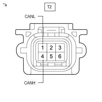
(b) Disconnect the T2 rear television camera assembly connector.
| (c) Measure the resistance according to the value(s) in the table below. Standard Resistance:
|
|
| NG | | REPAIR OR REPLACE CAN BRANCH LINES OR CONNECTOR (REAR TELEVISION CAMERA ASSEMBLY) |
|
| 3. | CHECK HARNESS AND CONNECTOR (POWER SOURCE CIRCUIT) |
| (a) Measure the resistance according to the value(s) in the table below. Standard Resistance:
|
|
.png)
(b) Reconnect the cable to the negative (-) battery terminal.
(c) Measure the voltage according to the value(s) in the table below.
Standard Voltage:
| Tester Connection | Condition | Specified Condition |
|---|---|---|
| T2-6 (CB+) - Body ground | Engine switch on (ACC) | 11 to 14 V |
| OK | | REPLACE REAR TELEVISION CAMERA ASSEMBLY |
| NG | | REPAIR OR REPLACE HARNESS OR CONNECTOR (POWER SOURCE CIRCUIT) |
| 4. | CHECK FOR OPEN IN CAN BUS LINES (REAR TELEVISION CAMERA ASSEMBLY BRANCH LINE) |
(a) Disconnect the cable from the negative (-) battery terminal.
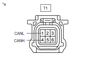
(b) Disconnect the T1 rear television camera assembly connector.
| (c) Measure the resistance according to the value(s) in the table below. Standard Resistance:
|
|
| NG | | REPAIR OR REPLACE CAN BRANCH LINES OR CONNECTOR (REAR TELEVISION CAMERA ASSEMBLY) |
|
| 5. | CHECK HARNESS AND CONNECTOR (POWER SOURCE CIRCUIT) |
| (a) Measure the resistance according to the value(s) in the table below. Standard Resistance:
|
|
.png)
(b) Reconnect the cable to the negative (-) battery terminal.
(c) Measure the voltage according to the value(s) in the table below.
Standard Voltage:
| Tester Connection | Condition | Specified Condition |
|---|---|---|
| T1-6 (CB+) - Body ground | Engine switch on (ACC) | 5.5 to 7.05 V |
| OK | | REPLACE REAR TELEVISION CAMERA ASSEMBLY |
| NG | | REPAIR OR REPLACE HARNESS OR CONNECTOR (POWER SOURCE CIRCUIT) |
READ NEXT:
 Millimeter Wave Radar Sensor Communication Stop Mode
DESCRIPTION Detection Item Symptom Trouble Area Millimeter Wave Radar Sensor Communication Stop Mode Any of the following conditions are met:
Communication stop for "Front Radar" is in
Headup Display Communication Stop Mode
DESCRIPTION Detection Item Symptom Trouble Area Headup Display Communication Stop Mode Any of the following conditions are met:
Communication stop for "Head Up Display" is indicated on
Door Mirror ECU RH Communication Stop Mode
DESCRIPTION Detection Item Symptom Trouble Area Door Mirror ECU RH Communication Stop Mode Any of the following conditions are met:
Communication stop for "Front Door RH/R-Mirror (FR-D
SEE MORE:
Left Front Wheel ABS Hold Solenoid Control Circuit Short to Battery (C12A512,...,C12B049)
DESCRIPTION The ABS solenoid relay and solenoid valves are built into the brake actuator assembly. The front solenoid valve LH controls the brake fluid pressure of the front wheel cylinder LH of the vehicle. When this DTC is stored, the fail-safe function operates and the ABS solenoid relay is turne
Tire Pressure Monitor ECU Communication Stop Mode
DESCRIPTION Detection Item Symptom Trouble Area Tire Pressure Monitor ECU Communication Stop Mode Any of the following conditions are met:
Communication stop for "Tire Pressure" is indicated on the "Communication Bus Check" screen of the Techstream.
Click here
Communication sto
