Lexus ES: Left Rear Wheel Speed Sensor Internal Electronic Failure (C050C49)
DESCRIPTION
When the system is starting up and the skid control ECU (brake actuator assembly) detects a speed sensor circuit malfunction via the speed sensor circuit self-diagnosis function, this DTC is stored.
| DTC No. | Detection Item | DTC Detection Condition | Trouble Area |
|---|---|---|---|
| C050C49 | Left Rear Wheel Speed Sensor Internal Electronic Failure | A circuit malfunction in the speed sensor is detected during the self test. |
|
*1: for 2WD
*2: for AWD
WIRING DIAGRAM
Refer to DTC C050C12.
Click here .gif)
CAUTION / NOTICE / HINT
NOTICE:
-
After replacing the skid control ECU (brake actuator assembly), perform acceleration sensor zero point calibration and store system information memorization.
Click here
-
After replacing or removing and installing a speed sensor, perform Dealer Mode (Signal Check) inspection to confirm that the speed sensors are operating correctly.
Click here
PROCEDURE
| 1. | CHECK VEHICLE |
(a) Check the vehicle specification.
| Result | Proceed to |
|---|---|
| for 2WD (w/o AVS) | A |
| for 2WD (w/ AVS) | B |
| for AWD | C |
| B |  | GO TO STEP 13 |
| C | | GO TO STEP 24 |
|

| 2. | CHECK HARNESS AND CONNECTOR (SENSOR CIRCUIT) |
| (a) Make sure that there is no looseness at the locking part and the connecting part of the connectors. OK: The connector is securely connected. |
|
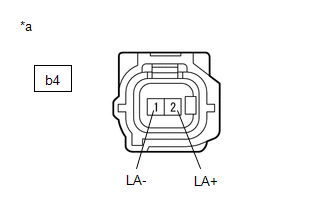
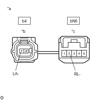
(b) Disconnect the b4 rear speed sensor LH (rear axle hub and bearing assembly LH) connector.
(c) Check both the connector case and the terminals for deformation and corrosion.
OK:
No deformation or corrosion.
(d) Turn the engine switch on (IG).
(e) Measure the voltage according to the value(s) in the table below.
Standard Voltage:
| Tester Connection | Condition | Specified Condition |
|---|---|---|
| b4-2 (LA+) - b4-1 (LA-) | Engine switch on (IG) | 11 to 14 V |
| NG | | GO TO STEP 8 |
|
| 3. | CHECK HARNESS AND CONNECTOR (SENSOR POWER SOURCE CIRCUIT) |
| (a) Make sure that there is no looseness at the locking part and the connecting part of the connectors. OK: The connector is securely connected. |
|
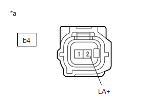
(b) Disconnect the b4 rear speed sensor LH (rear axle hub and bearing assembly LH) connector.
(c) Check both the connector case and the terminals for deformation and corrosion.
OK:
No deformation or corrosion.
(d) Measure the voltage according to the value(s) in the table below.
Standard Voltage:
| Tester Connection | Condition | Specified Condition |
|---|---|---|
| b4-2 (LA+) - Body ground | Engine switch off | Below 1.5 V |
| NG | | GO TO STEP 6 |
|
| 4. | INSPECT NO. 2 PARKING BRAKE WIRE ASSEMBLY |
| (a) Make sure that there is no looseness at the locking part and the connecting part of the connectors. OK: The connector is securely connected. |
|
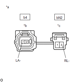
(b) Disconnect the b4 skid control sensor wire LH (No. 2 parking brake wire assembly) connector.
(c) Disconnect the bN2 skid control sensor wire LH (No. 2 parking brake wire assembly) connector.
(d) Check both the connector case and the terminals for deformation and corrosion.
OK:
No deformation or corrosion.
(e) Measure the resistance according to the value(s) in the table below.
Standard Resistance:
| Tester Connection | Condition | Specified Condition |
|---|---|---|
| b4-1 (LA-) or bN2-2 (RL-) - Body ground and other terminals | Always | 10 kΩ or higher |
| NG | | REPLACE NO. 2 PARKING BRAKE WIRE ASSEMBLY |
|
| 5. | CHECK HARNESS AND CONNECTOR (NO. 2 PARKING BRAKE WIRE ASSEMBLY - BRAKE ACTUATOR ASSEMBLY) |
(a) Make sure that there is no looseness at the locking part and the connecting part of the connectors.
OK:
The connector is securely connected.
(b) Disconnect the A40 skid control ECU (brake actuator assembly) connector.
(c) Disconnect the bN2 skid control sensor wire LH (No. 2 parking brake wire assembly) connector.
(d) Check both the connector case and the terminals for deformation and corrosion.
OK:
No deformation or corrosion.
(e) Measure the resistance according to the value(s) in the table below.
Standard Resistance:
| Tester Connection | Condition | Specified Condition |
|---|---|---|
| bN2-2 (RL-) or A40-23 (RL-) - Body ground | Always | 10 kΩ or higher |
| OK | | REPLACE REAR AXLE HUB AND BEARING ASSEMBLY LH |
| NG | | REPAIR OR REPLACE HARNESS OR CONNECTOR |
| 6. | CHECK HARNESS AND CONNECTOR (SENSOR POWER SOURCE CIRCUIT) |
| (a) Make sure that there is no looseness at the locking part and the connecting part of the connectors. OK: The connector is securely connected. |
|

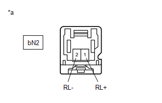
(b) Disconnect the bN2 skid control sensor wire LH (No. 2 parking brake wire assembly) connector.
(c) Check both the connector case and the terminals for deformation and corrosion.
OK:
No deformation or corrosion.
(d) Measure the voltage according to the value(s) in the table below.
Standard Voltage:
| Tester Connection | Condition | Specified Condition |
|---|---|---|
| bN2-1 (RL+) - Body ground | Engine switch off | Below 1.5 V |
| OK | | REPLACE NO. 2 PARKING BRAKE WIRE ASSEMBLY |
|
| 7. | CHECK HARNESS AND CONNECTOR (NO. 2 PARKING BRAKE WIRE ASSEMBLY - BRAKE ACTUATOR ASSEMBLY) |
| (a) Make sure that there is no looseness at the locking part and the connecting part of the connectors. OK: The connector is securely connected. |
|
(b) Disconnect the A40 skid control ECU (brake actuator assembly) connector.
(c) Disconnect the bN2 skid control sensor wire LH (No. 2 parking brake wire assembly) connector.
(d) Check both the connector case and the terminals for deformation and corrosion.
OK:
No deformation or corrosion.
(e) Measure the voltage according to the value(s) in the table below.
Standard Voltage:
| Tester Connection | Condition | Specified Condition |
|---|---|---|
| bN2-1 (RL+) - Body ground | Always | Below 1.5 V |
| OK | | REPLACE BRAKE ACTUATOR ASSEMBLY |
| NG | | REPAIR OR REPLACE HARNESS OR CONNECTOR |
| 8. | CHECK HARNESS AND CONNECTOR (SENSOR CIRCUIT) |
| (a) Make sure that there is no looseness at the locking part and the connecting part of the connectors. OK: The connector is securely connected. |
|
(b) Disconnect the bN2 skid control sensor wire LH (No. 2 parking brake wire assembly) connector.
(c) Check both the connector case and the terminals for deformation and corrosion.
OK:
No deformation or corrosion.
(d) Turn the engine switch on (IG).
(e) Measure the voltage according to the value(s) in the table below.
Standard Voltage:
| Tester Connection | Condition | Specified Condition |
|---|---|---|
| bN2-1 (RL+) - bN2-2 (RL-) | Engine switch on (IG) | 11 to 14 V |
| OK | | REPLACE NO. 2 PARKING BRAKE WIRE ASSEMBLY |
|
| 9. | CHECK HARNESS AND CONNECTOR (SENSOR POWER SOURCE CIRCUIT) |
| (a) Make sure that there is no looseness at the locking part and the connecting part of the connectors. OK: The connector is securely connected. |
|
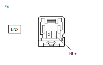
(b) Disconnect the bN2 skid control sensor wire LH (No. 2 parking brake wire assembly) connector.
(c) Check both the connector case and the terminals for deformation and corrosion.
OK:
No deformation or corrosion.
(d) Turn the engine switch on (IG).
(e) Measure the voltage according to the value(s) in the table below.
Standard Voltage:
| Tester Connection | Condition | Specified Condition |
|---|---|---|
| bN2-1 (RL+) - Body ground | Engine switch on (IG) | 11 to 14 V |
| NG | | GO TO STEP 12 |
|
| 10. | CHECK HARNESS AND CONNECTOR (NO. 2 PARKING BRAKE WIRE ASSEMBLY - BRAKE ACTUATOR ASSEMBLY) |
| (a) Make sure that there is no looseness at the locking part and the connecting part of the connectors. OK: The connector is securely connected. |
|

(b) Disconnect the A40 skid control ECU (brake actuator assembly) connector.
(c) Disconnect the bN2 skid control sensor wire LH (No. 2 parking brake wire assembly) connector.
(d) Check both the connector case and the terminals for deformation and corrosion.
OK:
No deformation or corrosion.
(e) Measure the voltage according to the value(s) in the table below.
Standard Voltage:
| Tester Connection | Condition | Specified Condition |
|---|---|---|
| bN2-2 (RL-) - Body ground | Always | Below 1.5 V |
| NG | | REPAIR OR REPLACE HARNESS OR CONNECTOR |
|
| 11. | CHECK HARNESS AND CONNECTOR (NO. 2 PARKING BRAKE WIRE ASSEMBLY - BRAKE ACTUATOR ASSEMBLY) |
(a) Make sure that there is no looseness at the locking part and the connecting part of the connectors.
OK:
The connector is securely connected.
(b) Disconnect the A40 skid control ECU (brake actuator assembly) connector.
(c) Disconnect the bN2 skid control sensor wire LH (No. 2 parking brake wire assembly) connector.
(d) Check both the connector case and the terminals for deformation and corrosion.
OK:
No deformation or corrosion.
(e) Measure the resistance according to the value(s) in the table below.
Standard Resistance:
| Tester Connection | Condition | Specified Condition |
|---|---|---|
| bN2-2 (RL-) - A40-23 (RL-) | Always | Below 1 Ω |
| bN2-1 (RL+) or A40-39 (RL+) - bN2-2 (RL-) or A40-23 (RL-) | Always | 10 kΩ or higher |
| OK | | REPLACE BRAKE ACTUATOR ASSEMBLY |
| NG | | REPAIR OR REPLACE HARNESS OR CONNECTOR |
| 12. | CHECK HARNESS AND CONNECTOR (NO. 2 PARKING BRAKE WIRE ASSEMBLY - BRAKE ACTUATOR ASSEMBLY) |
(a) Make sure that there is no looseness at the locking part and the connecting part of the connectors.
OK:
The connector is securely connected.
(b) Disconnect the A40 skid control ECU (brake actuator assembly) connector.
(c) Disconnect the bN2 skid control sensor wire LH (No. 2 parking brake wire assembly) connector.
(d) Check both the connector case and the terminals for deformation and corrosion.
OK:
No deformation or corrosion.
(e) Measure the resistance according to the value(s) in the table below.
Standard Resistance:
| Tester Connection | Condition | Specified Condition |
|---|---|---|
| bN2-1 (RL+) - A40-39 (RL+) | Always | Below 1 Ω |
| bN2-1 (RL+) or A40-39 (RL+) - Body ground | Always | 10 kΩ or higher |
| OK | | REPLACE BRAKE ACTUATOR ASSEMBLY |
| NG | | REPAIR OR REPLACE HARNESS OR CONNECTOR |
| 13. | CHECK HARNESS AND CONNECTOR (SENSOR CIRCUIT) |
| (a) Make sure that there is no looseness at the locking part and the connecting part of the connectors. OK: The connector is securely connected. |
|
(b) Disconnect the b4 rear speed sensor LH (rear axle hub and bearing assembly LH) connector.
(c) Check both the connector case and the terminals for deformation and corrosion.
OK:
No deformation or corrosion.
(d) Turn the engine switch on (IG).
(e) Measure the voltage according to the value(s) in the table below.
Standard Voltage:
| Tester Connection | Condition | Specified Condition |
|---|---|---|
| b4-2 (LA+) - b4-1 (LA-) | Engine switch on (IG) | 11 to 14 V |
| NG | | GO TO STEP 19 |
|
| 14. | CHECK HARNESS AND CONNECTOR (SENSOR POWER SOURCE CIRCUIT) |
| (a) Make sure that there is no looseness at the locking part and the connecting part of the connectors. OK: The connector is securely connected. |
|
(b) Disconnect the b4 rear speed sensor LH (rear axle hub and bearing assembly LH) connector.
(c) Check both the connector case and the terminals for deformation and corrosion.
OK:
No deformation or corrosion.
(d) Measure the voltage according to the value(s) in the table below.
Standard Voltage:
| Tester Connection | Condition | Specified Condition |
|---|---|---|
| b4-2 (LA+) - Body ground | Engine switch off | Below 1.5 V |
| NG | | GO TO STEP 17 |
|
| 15. | INSPECT NO. 2 PARKING BRAKE WIRE ASSEMBLY |
| (a) Make sure that there is no looseness at the locking part and the connecting part of the connectors. OK: The connector is securely connected. |
|
(b) Disconnect the b4 skid control sensor wire LH (No. 2 parking brake wire assembly) connector.
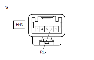
(c) Disconnect the bN6 skid control sensor wire LH (No. 2 parking brake wire assembly) connector.
(d) Check both the connector case and the terminals for deformation and corrosion.
OK:
No deformation or corrosion.
(e) Measure the resistance according to the value(s) in the table below.
Standard Resistance:
| Tester Connection | Condition | Specified Condition |
|---|---|---|
| b4-1 (LA-) or bN6-2 (RL-) - Body ground and other terminals | Always | 10 kΩ or higher |
| NG | | REPLACE NO. 2 PARKING BRAKE WIRE ASSEMBLY |
|
| 16. | CHECK HARNESS AND CONNECTOR (NO. 2 PARKING BRAKE WIRE ASSEMBLY - BRAKE ACTUATOR ASSEMBLY) |
(a) Make sure that there is no looseness at the locking part and the connecting part of the connectors.
OK:
The connector is securely connected.
(b) Disconnect the A40 skid control ECU (brake actuator assembly) connector.
(c) Disconnect the bN6 skid control sensor wire LH (No. 2 parking brake wire assembly) connector.
(d) Check both the connector case and the terminals for deformation and corrosion.
OK:
No deformation or corrosion.
(e) Measure the resistance according to the value(s) in the table below.
Standard Resistance:
| Tester Connection | Condition | Specified Condition |
|---|---|---|
| bN6-2 (RL-) or A40-23 (RL-) - Body ground | Always | 10 kΩ or higher |
| OK | | REPLACE REAR AXLE HUB AND BEARING ASSEMBLY LH |
| NG | | REPAIR OR REPLACE HARNESS OR CONNECTOR |
| 17. | CHECK HARNESS AND CONNECTOR (SENSOR POWER SOURCE CIRCUIT) |
| (a) Make sure that there is no looseness at the locking part and the connecting part of the connectors. OK: The connector is securely connected. |
|
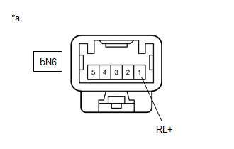
(b) Disconnect the bN6 skid control sensor wire LH (No. 2 parking brake wire assembly) connector.
(c) Check both the connector case and the terminals for deformation and corrosion.
OK:
No deformation or corrosion.
(d) Measure the voltage according to the value(s) in the table below.
Standard Voltage:
| Tester Connection | Condition | Specified Condition |
|---|---|---|
| bN6-1 (RL+) - Body ground | Engine switch off | Below 1.5 V |
| OK | | REPLACE NO. 2 PARKING BRAKE WIRE ASSEMBLY |
|
| 18. | CHECK HARNESS AND CONNECTOR (NO. 2 PARKING BRAKE WIRE ASSEMBLY - BRAKE ACTUATOR ASSEMBLY) |
| (a) Make sure that there is no looseness at the locking part and the connecting part of the connectors. OK: The connector is securely connected. |
|
(b) Disconnect the A40 skid control ECU (brake actuator assembly) connector.
(c) Disconnect the bN6 skid control sensor wire LH (No. 2 parking brake wire assembly) connector.
(d) Check both the connector case and the terminals for deformation and corrosion.
OK:
No deformation or corrosion.
(e) Measure the voltage according to the value(s) in the table below.
Standard Voltage:
| Tester Connection | Condition | Specified Condition |
|---|---|---|
| bN6-1 (RL+) - Body ground | Always | Below 1.5 V |
| OK | | REPLACE BRAKE ACTUATOR ASSEMBLY |
| NG | | REPAIR OR REPLACE HARNESS OR CONNECTOR |
| 19. | CHECK HARNESS AND CONNECTOR (SENSOR CIRCUIT) |
| (a) Make sure that there is no looseness at the locking part and the connecting part of the connectors. OK: The connector is securely connected. |
|
(b) Disconnect the bN6 skid control sensor wire LH (No. 2 parking brake wire assembly) connector.
(c) Check both the connector case and the terminals for deformation and corrosion.
OK:
No deformation or corrosion.
(d) Turn the engine switch on (IG).
(e) Measure the voltage according to the value(s) in the table below.
Standard Voltage:
| Tester Connection | Condition | Specified Condition |
|---|---|---|
| bN6-1 (RL+) - bN6-2 (RL-) | Engine switch on (IG) | 11 to 14 V |
| OK | | REPLACE NO. 2 PARKING BRAKE WIRE ASSEMBLY |
|
| 20. | CHECK HARNESS AND CONNECTOR (SENSOR POWER SOURCE CIRCUIT) |
| (a) Make sure that there is no looseness at the locking part and the connecting part of the connectors. OK: The connector is securely connected. |
|
(b) Disconnect the bN6 skid control sensor wire LH (No. 2 parking brake wire assembly) connector.
(c) Check both the connector case and the terminals for deformation and corrosion.
OK:
No deformation or corrosion.
(d) Turn the engine switch on (IG).
(e) Measure the voltage according to the value(s) in the table below.
Standard Voltage:
| Tester Connection | Condition | Specified Condition |
|---|---|---|
| bN6-1 (RL+) - Body ground | Engine switch on (IG) | 11 to 14 V |
| NG | | GO TO STEP 23 |
|
| 21. | CHECK HARNESS AND CONNECTOR (NO. 2 PARKING BRAKE WIRE ASSEMBLY - BRAKE ACTUATOR ASSEMBLY) |
| (a) Make sure that there is no looseness at the locking part and the connecting part of the connectors. OK: The connector is securely connected. |
|
(b) Disconnect the A40 skid control ECU (brake actuator assembly) connector.
(c) Disconnect the bN6 skid control sensor wire LH (No. 2 parking brake wire assembly) connector.
(d) Check both the connector case and the terminals for deformation and corrosion.
OK:
No deformation or corrosion.
(e) Measure the voltage according to the value(s) in the table below.
Standard Voltage:
| Tester Connection | Condition | Specified Condition |
|---|---|---|
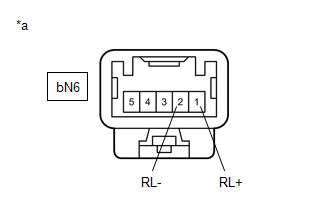
| bN6-2 (RL-) - Body ground | Always | Below 1.5 V |
| NG | | REPAIR OR REPLACE HARNESS OR CONNECTOR |
|
| 22. | CHECK HARNESS AND CONNECTOR (NO. 2 PARKING BRAKE WIRE ASSEMBLY - BRAKE ACTUATOR ASSEMBLY) |
(a) Make sure that there is no looseness at the locking part and the connecting part of the connectors.
OK:
The connector is securely connected.
(b) Disconnect the A40 skid control ECU (brake actuator assembly) connector.
(c) Disconnect the bN6 skid control sensor wire LH (No. 2 parking brake wire assembly) connector.
(d) Check both the connector case and the terminals for deformation and corrosion.
OK:
No deformation or corrosion.
(e) Measure the resistance according to the value(s) in the table below.
Standard Resistance:
| Tester Connection | Condition | Specified Condition |
|---|---|---|
| bN6-2 (RL-) - A40-23 (RL-) | Always | Below 1 Ω |
| bN6-1 (RL+) or A40-39 (RL+) - bN6-2 (RL-) or A40-23 (RL-) | Always | 10 kΩ or higher |
| OK | | REPLACE BRAKE ACTUATOR ASSEMBLY |
| NG | | REPAIR OR REPLACE HARNESS OR CONNECTOR |
| 23. | CHECK HARNESS AND CONNECTOR (NO. 2 PARKING BRAKE WIRE ASSEMBLY - BRAKE ACTUATOR ASSEMBLY) |
(a) Make sure that there is no looseness at the locking part and the connecting part of the connectors.
OK:
The connector is securely connected.
(b) Disconnect the A40 skid control ECU (brake actuator assembly) connector.
(c) Disconnect the bN6 skid control sensor wire LH (No. 2 parking brake wire assembly) connector.
(d) Check both the connector case and the terminals for deformation and corrosion.
OK:
No deformation or corrosion.
(e) Measure the resistance according to the value(s) in the table below.
Standard Resistance:
| Tester Connection | Condition | Specified Condition |
|---|---|---|
| bN6-1 (RL+) - A40-39 (RL+) | Always | Below 1 Ω |
| bN6-1 (RL+) or A40-39 (RL+) - Body ground | Always | 10 kΩ or higher |
| OK | | REPLACE BRAKE ACTUATOR ASSEMBLY |
| NG | | REPAIR OR REPLACE HARNESS OR CONNECTOR |
| 24. | CHECK HARNESS AND CONNECTOR (SENSOR CIRCUIT) |
| (a) Make sure that there is no looseness at the locking part and the connecting part of the connectors. OK: The connector is securely connected. |
|
(b) Disconnect the b4 rear speed sensor LH connector.
(c) Check both the connector case and the terminals for deformation and corrosion.
OK:
No deformation or corrosion.
(d) Turn the engine switch on (IG).
(e) Measure the voltage according to the value(s) in the table below.
Standard Voltage:
| Tester Connection | Condition | Specified Condition |
|---|---|---|
| b4-2 (LA+) - b4-1 (LA-) | Engine switch on (IG) | 11 to 14 V |
| NG | | GO TO STEP 8 |
|
| 25. | CHECK HARNESS AND CONNECTOR (SENSOR POWER SOURCE CIRCUIT) |
| (a) Make sure that there is no looseness at the locking part and the connecting part of the connectors. OK: The connector is securely connected. |
|
(b) Disconnect the b4 rear speed sensor LH connector.
(c) Check both the connector case and the terminals for deformation and corrosion.
OK:
No deformation or corrosion.
(d) Measure the voltage according to the value(s) in the table below.
Standard Voltage:
| Tester Connection | Condition | Specified Condition |
|---|---|---|
| b4-2 (LA+) - Body ground | Engine switch off | Below 1.5 V |
| NG | | GO TO STEP 6 |
|
| 26. | INSPECT NO. 2 PARKING BRAKE WIRE ASSEMBLY |
| (a) Make sure that there is no looseness at the locking part and the connecting part of the connectors. OK: The connector is securely connected. |
|
(b) Disconnect the b4 skid control sensor wire LH (No. 2 parking brake wire assembly) connector.
(c) Disconnect the bN2 skid control sensor wire LH (No. 2 parking brake wire assembly) connector.
(d) Check both the connector case and the terminals for deformation and corrosion.
OK:
No deformation or corrosion.
(e) Measure the resistance according to the value(s) in the table below.
Standard Resistance:
| Tester Connection | Condition | Specified Condition |
|---|---|---|
| b4-1 (LA-) or bN2-2 (RL-) - Body ground and other terminals | Always | 10 kΩ or higher |
| NG | | REPLACE NO. 2 PARKING BRAKE WIRE ASSEMBLY |
|
| 27. | CHECK HARNESS AND CONNECTOR (NO. 2 PARKING BRAKE WIRE ASSEMBLY - BRAKE ACTUATOR ASSEMBLY) |
(a) Make sure that there is no looseness at the locking part and the connecting part of the connectors.
OK:
The connector is securely connected.
(b) Disconnect the A40 skid control ECU (brake actuator assembly) connector.
(c) Disconnect the bN2 skid control sensor wire LH (No. 2 parking brake wire assembly) connector.
(d) Check both the connector case and the terminals for deformation and corrosion.
OK:
No deformation or corrosion.
(e) Measure the resistance according to the value(s) in the table below.
Standard Resistance:
| Tester Connection | Condition | Specified Condition |
|---|---|---|
| bN2-2 (RL-) or A40-23 (RL-) - Body ground | Always | 10 kΩ or higher |
| OK | | REPLACE REAR SPEED SENSOR LH |
| NG | | REPAIR OR REPLACE HARNESS OR CONNECTOR |
READ NEXT:
 Multi-axis Acceleration Sensor Module "A" Missing Calibration (C051D54)
DESCRIPTION The airbag ECU assembly has a built-in yaw rate and acceleration sensor and detects the vehicle condition. The skid control ECU (brake actuator assembly) receives signals from the yaw rate
ABS Pump Motor Control Circuit Short to Ground (C052C11,C052C13,C142719)
DESCRIPTION The ABS motor relay is built into the brake actuator assembly. When the skid control ECU (brake actuator assembly) operates ABS, TRAC, VSC, brake hold or brake assist, the ABS motor relay
ABS Pump Motor Control Internal Electronic Failure (C052C49)
DESCRIPTION The ABS motor relay and pump motor are built into the brake actuator assembly. If the skid control ECU (brake actuator assembly) detects a malfunction in the drive circuit of the pump moto
SEE MORE:
Installation
INSTALLATION CAUTION / NOTICE / HINT HINT:
Use the same procedure for the RH side and LH side.
The following procedure is for the LH side.
PROCEDURE 1. INSTALL NO. 3 WINDSHIELD OUTSIDE MOULDING CLIP HINT: Perform the following procedure only when replacement of a No. 3 windshield outside mou
Shutter Control State Maintenance Mode (B1333)
DESCRIPTION This DTC is stored when the grille shutter system is changed to maintenance mode. DTC No. Detection Item DTC Detection Condition Trouble Area B1333 Shutter Control State Maintenance Mode The grille shutter system is changed to maintenance mode. Swing grille actuator as
