Lexus ES: Installation
INSTALLATION
PROCEDURE
1. INSTALL HOLE PLUG
| (a) Install the 10 hole plugs to the rear suspension member sub-assembly. HINT: There are 2 different shapes of hole plug. |
|
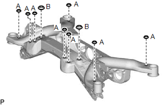
2. INSTALL REAR SUSPENSION MEMBER FRONT BODY MOUNTING CUSHION (for LH Side)
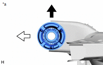
(a) Confirm the installation direction and temporarily install a new rear suspension member front body mounting cushion.
NOTICE:
- Position the rear suspension member front body mounting cushion in the correct direction.
- Do not apply lubricant to the outer sleeve of the rear suspension member front body mounting cushion.
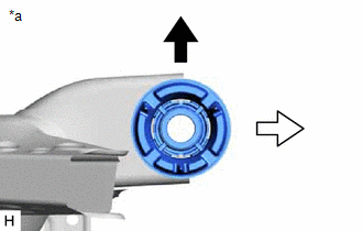
| *a | View from Underneath |
.png) | Front of the Vehicle |
.png) | Outside of the Vehicle |
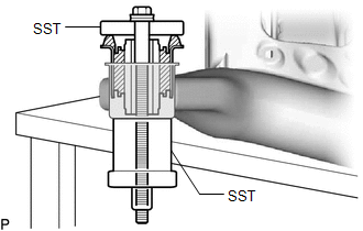
| (b) Install SST as shown in the illustration. SST: 09570-24011 SST: 09830-10010 09830-01010 09830-01020 09830-01040 09830-01050 NOTICE: Apply molybdenum grease to the threads and tip of the SST center bolt before use. |
|
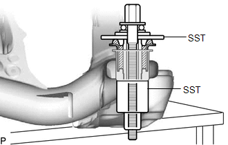
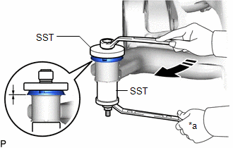
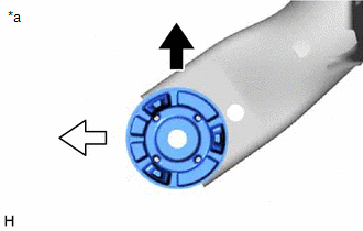
(c) Using SST, install the rear suspension member front body mounting cushion until there is no clearance between the rear suspension member sub-assembly and rear suspension member front body mounting cushion.
SST: 09570-24011
SST: 09830-10010
09830-01010
09830-01020
09830-01040
09830-01050
NOTICE:
If the rear suspension member sub-assembly is scratched, apply paint to the scratched areas of the rear suspension member sub-assembly.
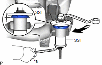
| *a | Hold |
.png) | Turn |
(d) Remove SST from the rear suspension member sub-assembly.
3. INSTALL REAR SUSPENSION MEMBER FRONT BODY MOUNTING CUSHION (for RH Side)
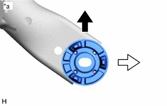
(a) Confirm the installation direction and temporarily install a new rear suspension member front body mounting cushion.
NOTICE:
- Position the rear suspension member front body mounting cushion in the correct direction.
- Do not apply lubricant to the outer sleeve of the rear suspension member front body mounting cushion.
| *a | View from Underneath |
| | Front of the Vehicle |
| | Outside of the Vehicle |
(b) Install SST using the same procedure as for the rear suspension member front body mounting cushion (for LH Side).
SST: 09570-24011
SST: 09830-10010
09830-01010
09830-01020
09830-01040
09830-01050
NOTICE:
Apply molybdenum grease to the threads and tip of the SST center bolt before use.
(c) Using SST, install the rear suspension member front body mounting cushion until there is no clearance between the rear suspension member sub-assembly and rear suspension member front body mounting cushion.
SST: 09570-24011
SST: 09830-10010
09830-01010
09830-01020
09830-01040
09830-01050
NOTICE:
If the rear suspension member sub-assembly is scratched, apply paint to the scratched areas of the rear suspension member sub-assembly.
HINT:
Perform the same procedure as for the rear suspension member front body mounting cushion (for LH Side).
(d) Remove SST from the rear suspension member sub-assembly.
4. INSTALL REAR SUSPENSION MEMBER REAR BODY MOUNT CUSHION LH
(a) Confirm the installation direction and temporarily install a new rear suspension member rear body mount cushion LH.
NOTICE:
- Position the rear suspension member rear body mount cushion LH in the correct direction.
- Do not apply lubricant to the outer sleeve of the rear suspension member rear body mount cushion LH.
| *a | View from Underneath |
| | Front of the Vehicle |
| | Outside of the Vehicle |
| (b) Install SST as shown in the illustration. SST: 09710-28031 09711-02030 09711-02040 94622-51200 SST: 09950-60021 09951-00720 09951-00890 NOTICE: Apply molybdenum grease to the threads and tip of the SST center bolt before use. |
|
(c) Using SST, install the rear suspension member rear body mount cushion LH until there is no clearance between the rear suspension member sub-assembly and rear suspension member rear body mount cushion LH.
SST: 09710-28031
09711-02030
09711-02040
94622-51200
SST: 09950-60021
09951-00720
09951-00890
NOTICE:
If the rear suspension member sub-assembly is scratched, apply paint to the scratched areas of the rear suspension member sub-assembly.
| *a | Hold |
| | Turn |
(d) Remove SST from the rear suspension member sub-assembly.
5. INSTALL REAR SUSPENSION MEMBER REAR BODY MOUNT CUSHION RH
(a) Confirm the installation direction and temporarily install a new rear suspension member rear body mount cushion RH.
NOTICE:
- Position the rear suspension member rear body mount cushion RH in the correct direction.
- Do not apply lubricant to the outer sleeve of the rear suspension member rear body mount cushion RH.
| *a | View from Underneath |
| | Front of the Vehicle |
| | Outside of the Vehicle |
(b) Install SST using the same procedure as for the rear suspension member rear body mount cushion LH.
SST: 09710-28031
09711-02030
09711-02040
94622-51200
SST: 09950-60021
09951-00720
09951-00890
NOTICE:
Apply molybdenum grease to the threads and tip of the SST center bolt before use.
(c) Using SST, install the rear suspension member rear body mount cushion RH until there is no clearance between the rear suspension member sub-assembly and rear suspension member rear body mount cushion RH.
SST: 09710-28031
09711-02030
09711-02040
94622-51200
SST: 09950-60021
09951-00720
09951-00890
NOTICE:
If the rear suspension member sub-assembly is scratched, apply paint to the scratched areas of the rear suspension member sub-assembly.
HINT:
Perform the same procedure as for the rear suspension member rear body mount cushion LH.
(d) Remove SST from the rear suspension member sub-assembly.
6. INSTALL REAR UPPER CONTROL ARM ASSEMBLY LH
Click here .gif)
7. INSTALL REAR UPPER CONTROL ARM ASSEMBLY RH
HINT:
Perform the same procedure as for the LH side.
8. INSTALL WIRE HARNESS
(a) Engage the 2 clamps and install the wire harness to the rear suspension member sub-assembly.
9. INSTALL REAR SUSPENSION MEMBER SUB-ASSEMBLY
(a) Install the 4 rear suspension member cushions to the rear suspension member sub-assembly.
HINT:
When reusing the rear suspension member cushion, make sure to check its identification mark and install it to the correct position.
(b) Using an engine lifter and 4 attachments or equivalent tools, support the rear suspension member sub-assembly as shown in the illustration.
.png)
- The rear suspension member sub-assembly is a very heavy component. Make sure that it is supported securely.
- If the rear suspension member sub-assembly is not securely supported, it may drop, resulting in serious injury.
NOTICE:
- Use attachments or equivalent tools to keep the rear suspension member sub-assembly level.
- Keep supporting the rear suspension member sub-assembly until the installation has been completed.
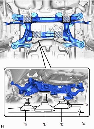
| *a | Engine Lifter |
| *b | Attachment |
.png) | Attachment Placement Location |
(c) Raise the rear suspension member sub-assembly until there is no clearance between the rear suspension member sub-assembly and vehicle.
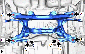
| (d) Install the rear suspension member sub-assembly with the 2 rear suspension member lower stoppers, rear suspension member lower brace LH and rear suspension member lower brace RH, 2 bolts and 6 nuts. Torque: Bolt A : 158 N·m {1611 kgf·cm, 117 ft·lbf} Nut B : 158 N·m {1611 kgf·cm, 117 ft·lbf} Nut C : 18 N·m {184 kgf·cm, 13 ft·lbf} |
|
(e) Pass the connector through the hole to the inside of the vehicle and install the grommet of the wire harness.
(f) Connect the connector.
10. INSTALL REAR SEAT ASSEMBLY
Click here
11. TEMPORARILY INSTALL REAR NO. 2 SUSPENSION ARM ASSEMBLY LH
Click here
12. TEMPORARILY INSTALL REAR NO. 2 SUSPENSION ARM ASSEMBLY RH
HINT:
Perform the same procedure as for the LH side.
13. INSTALL REAR NO. 1 DIFFERENTIAL MOUNT CUSHION
Click here
14. INSTALL REAR DIFFERENTIAL CARRIER ASSEMBLY
Click here
READ NEXT:
 Problem Symptoms Table
PROBLEM SYMPTOMS TABLE HINT: Use the table below to help determine the cause of problem symptoms. If multiple suspected areas are listed, the potential causes of the symptoms are listed in order of pr
Problem Symptoms Table
PROBLEM SYMPTOMS TABLE HINT: Use the table below to help determine the cause of problem symptoms. If multiple suspected areas are listed, the potential causes of the symptoms are listed in order of pr
SEE MORE:
Components
COMPONENTS ILLUSTRATION *1 FRONT WHEEL OPENING EXTENSION PAD RH *2 FRONT WHEEL OPENING EXTENSION PAD LH *3 NO. 1 ENGINE UNDER COVER *4 NO. 2 ENGINE UNDER COVER ASSEMBLY N*m (kgf*cm, ft.*lbf): Specified torque - - ILLUSTRATION *1 DRIVE SHAFT BEARING BRACKET *
Dtc Check / Clear
DTC CHECK / CLEAR NOTICE: When the diagnosis system is changed from normal mode to check mode or vice versa, all DTCs and Freeze Frame Data recorded in normal mode are cleared. Before changing modes, always check and make a note of DTCs and Freeze Frame Data. HINT:
DTCs which are stored in the EC
