Lexus ES: Installation
INSTALLATION
CAUTION / NOTICE / HINT
NOTICE:
This procedure includes the installation of small-head bolts. Refer to Small-Head Bolts of Basic Repair Hint to identify the small-head bolts.
Click here .gif)
PROCEDURE
1. INSTALL THROTTLE BODY GASKET
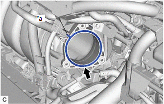
| (a) Install a new throttle body gasket to the intake manifold with the protrusion of the throttle body gasket oriented as shown in the illustration. |
|
2. INSTALL THROTTLE BODY WITH MOTOR ASSEMBLY
HINT:
Perform "Inspection After Repair" after replacing the throttle body with motor assembly.
Click here
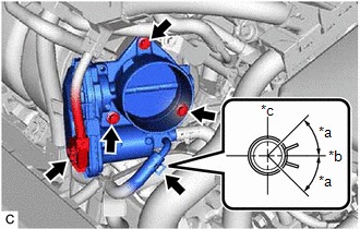
| (a) Connect the No. 6 water by-pass hose to the throttle body with motor assembly and slide the clip to secure it. NOTICE:
|
|
| (b) Using an 8 mm socket wrench, install the throttle body with motor assembly to the intake manifold with the 3 bolts. Torque: 10 N·m {102 kgf·cm, 7 ft·lbf} |
|
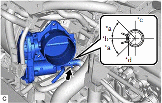
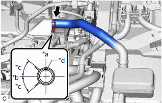
(c) Connect the No. 5 water by-pass hose to the throttle body with motor assembly and slide the clip to secure it.
NOTICE:
Make sure to position the clip as shown in the illustration.
(d) Connect the throttle body with motor assembly connector.
3. INSTALL AIR CLEANER CAP WITH AIR CLEANER HOSE
| (a) Install the air cleaner cap with air cleaner hose to the throttle body with motor assembly. NOTICE: Align the cutout of the air cleaner hose assembly with the protrusion of the throttle body with motor assembly. |
|
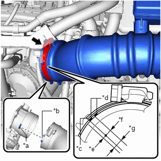
(b) Tighten the hose clamp in the position shown in the illustration.
NOTICE:
Make sure that the end of the hose clamp is positioned as shown in the illustration.
(c) Engage the 2 guides to install the air cleaner cap sub-assembly to the air cleaner case sub-assembly.
(d) Engage the 2 air cleaner cap clamps.
| (e) Connect the No. 2 ventilation hose to the cylinder head cover sub-assembly and slide the clip to secure it. NOTICE: Make sure to position the clip as shown in the illustration. |
|
(f) Engage the wire harness clamp.
(g) Connect the mass air flow meter sub-assembly connector.
4. INSTALL INLET AIR CLEANER ASSEMBLY
Click here
5. INSTALL COOL AIR INTAKE DUCT SEAL
Click here
6. INSTALL NO. 1 ENGINE COVER SUB-ASSEMBLY
Click here
7. ADD ENGINE COOLANT (for Engine)
Click here
8. INSPECT FOR COOLANT LEAK (for Engine)
Click here
9. PERFORM INITIALIZATION
NOTICE:
- Be sure to perform this procedure after removing and reinstalling the throttle body with motor assembly or any throttle body with motor assembly components.
- Perform the following procedure after replacing the throttle body with motor assembly or any throttle body with motor assembly components. The following procedure should also be performed if the throttle body with motor assembly is cleaned.
(a) Connect the Techstream to the DLC3.
(b) Turn the power switch on (IG).
(c) Turn the Techstream on.
(d) Clear the DTCs.
Powertrain > Engine > Clear DTCs(e) Perform "Inspection After Repair".
Click here
(f) Put the engine in Inspection Mode (Maintenance Mode).
Powertrain > Hybrid Control > Utility| Tester Display |
|---|
| Inspection Mode |
(g) Start the engine and check that the MIL is not illuminated. After the engine is warmed up, check that the idle speed is within the specified range with the A/C switch off.
Standard Idle Speed:
1050 to 1150 rpm
NOTICE:
- Be sure to perform this step with all accessories off.
- Make sure that the shift lever is in P.
(h) Perform a road test and confirm that there are no abnormalities.
READ NEXT:
 Components
COMPONENTS ILLUSTRATION *1 IGNITION COIL ASSEMBLY *2 ENGINE WIRE *3 CAM TIMING OIL CONTROL SOLENOID ASSEMBLY *4 CAM TIMING CONTROL MOTOR WITH EDU ASSEMBLY *5 CYLINDER HEAD CO
SEE MORE:
Data List / Active Test
DATA LIST / ACTIVE TEST READ DATA LIST HINT: Using the Techstream to read the Data List allows the values or states of switches, sensors, actuators and other items to be read without removing any parts. This non-intrusive inspection can be very useful because intermittent conditions or signals may b
System Diagram
SYSTEM DIAGRAM Communication Table Sender Receiver Signal Line Main Body ECU (Multiplex Network Body ECU) Sliding Roof ECU (Sliding Roof Drive Gear Sub-assembly)
Sliding roof operation permission signal
IG signal
Front door courtesy light switch assembly signal
Key-linked
