Lexus ES: Installation
INSTALLATION
CAUTION / NOTICE / HINT
NOTICE:
This procedure includes the installation of small-head bolts. Refer to Small-Head Bolts of Basic Repair Hint to identify the small-head bolts.
Click here .gif)
PROCEDURE
1. INSTALL KNOCK CONTROL SENSOR
HINT:
Perform "Inspection After Repair" after replacing the knock control sensor.
Click here
| (a) Install the knock control sensor to the cylinder block sub-assembly with the bolt so that the knock control sensor installation position is as shown in the illustration. Torque: 21 N·m {214 kgf·cm, 15 ft·lbf} NOTICE:
|
|
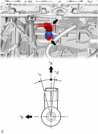
(b) Connect the knock control sensor connector.
2. INSTALL INTAKE MANIFOLD
Click here
3. PERFORM INITIALIZATION
(a) Perform "Inspection After Repair" after replacing the knock control sensor.
Click here
READ NEXT:
 Components
COMPONENTS ILLUSTRATION *1 MASS AIR FLOW METER SUB-ASSEMBLY - -
On-vehicle Inspection
ON-VEHICLE INSPECTION PROCEDURE 1. INSPECT MASS AIR FLOW METER SUB-ASSEMBLY HINT: Perform "Inspection After Repair" after replacing the mass air flow meter sub-assembly. Click here (a) Read the v
SEE MORE:
Installation
INSTALLATION PROCEDURE 1. INSTALL FUEL LID OPENER SWITCH (TRUNK AND FUEL SWITCH ASSEMBLY) (a) Engage the 2 claws to install the fuel lid opener switch (trunk and fuel switch assembly) as shown in the illustration. Install in this Direction 2. INSTALL LOWER INSTRUMENT PANEL FINISH PANEL SUB
Registration
REGISTRATION CAUTION / NOTICE / HINT PROCEDURE 1. VIN (VEHICLE IDENTIFICATION NUMBER) NOTICE: The Vehicle Identification Number (VIN) must be written to a replacement ECM. HINT: The VIN is a 17-digit alphanumeric vehicle identification number. The Techstream is required to register the VIN. (a) DESC
