Lexus ES: Components
COMPONENTS
ILLUSTRATION
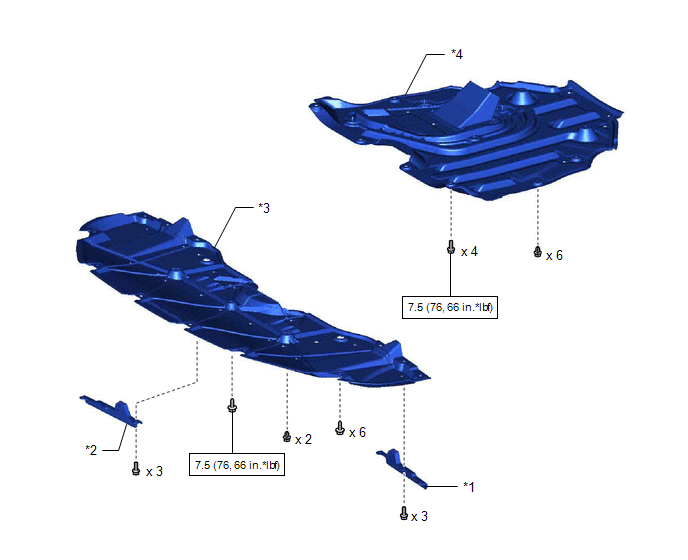
| *1 | FRONT WHEEL OPENING EXTENSION PAD LH | *2 | FRONT WHEEL OPENING EXTENSION PAD RH |
| *3 | NO. 1 ENGINE UNDER COVER | *4 | NO. 2 ENGINE UNDER COVER ASSEMBLY |
.png) | N*m (kgf*cm, ft.*lbf): Specified torque | - | - |
ILLUSTRATION
.png)
| *1 | FRONT BUMPER ENERGY ABSORBER | *2 | FRONT BUMPER REINFORCEMENT SUB-ASSEMBLY |
| *3 | NO. 2 FRONT BUMPER MOUNTING BRACKET | *4 | CLIP |
| | N*m (kgf*cm, ft.*lbf): Specified torque | ● | Non-reusable part |
ILLUSTRATION
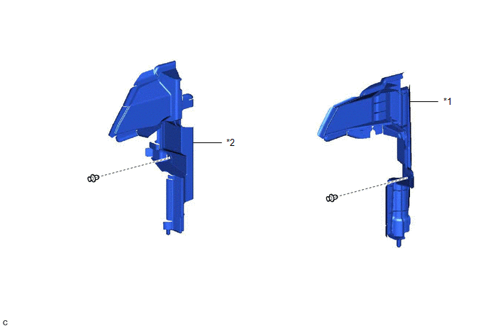
| *1 | NO. 1 RADIATOR AIR GUIDE LH | *2 | NO. 1 RADIATOR AIR GUIDE RH |
ILLUSTRATION
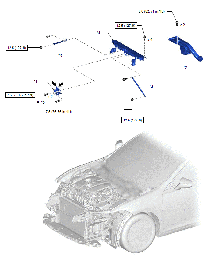
| *1 | HOOD LOCK ASSEMBLY | *2 | INLET AIR CLEANER ASSEMBLY |
| *3 | UPPER RADIATOR MOUNTING BRACKET | *4 | UPPER RADIATOR SUPPORT SUB-ASSEMBLY |
| *5 | HOOD LOCK NUT CAP | - | - |
| | N*m (kgf*cm, ft.*lbf): Specified torque | ● | Non-reusable part |
.png) | MP grease | - | - |
ILLUSTRATION
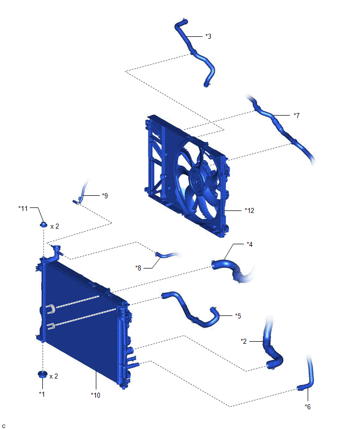
| *1 | LOWER RADIATOR SUPPORT | *2 | NO. 1 RADIATOR HOSE |
| *3 | NO. 2 INVERTER COOLING HOSE | *4 | NO. 2 RADIATOR HOSE |
| *5 | NO. 3 INVERTER COOLING HOSE | *6 | NO. 4 INVERTER COOLING HOSE |
| *7 | NO. 5 INVERTER COOLING HOSE | *8 | NO. 5 WATER BY-PASS HOSE |
| *9 | NO. 6 WATER BY-PASS HOSE | *10 | RADIATOR ASSEMBLY |
| *11 | RADIATOR SUPPORT CUSHION | *12 | FAN WITH MOTOR ASSEMBLY |
READ NEXT:
 On-vehicle Inspection
ON-VEHICLE INSPECTION CAUTION / NOTICE / HINT CAUTION: Do not remove the radiator cap sub-assembly while the engine and radiator assembly are still hot. Pressurized, hot engine coolant and steam may b
Removal
REMOVAL CAUTION / NOTICE / HINT The necessary procedures (adjustment, calibration, initialization or registration) that must be performed after parts are removed and installed, or replaced during radi
Installation
INSTALLATION PROCEDURE 1. INSTALL LOWER RADIATOR SUPPORT (a) Install the 2 lower radiator supports to the radiator assembly. 2. INSTALL RADIATOR SUPPORT CUSHION (a) Install the 2 radiator support cush
SEE MORE:
Back Camera Power Supply Failure (C1621)
DESCRIPTION This DTC is stored if the rear television camera assembly judges as a result of its self check that the signals or signal lines between the rear television camera assembly and multi-display assembly are not normal. DTC No. Detection Item DTC Detection Condition Trouble Area
VSC does not Operate or VSC does not Operate Correctly
DESCRIPTION When ABS, TRAC or VSC is operating, the skid control ECU (brake booster with master cylinder assembly) blinks the slip indicator light to inform the driver that slippage occurred. When a communication malfunction with the hybrid vehicle control ECU is detected, TRAC and VSC are disabled.
