Lexus ES: Installation
INSTALLATION
PROCEDURE
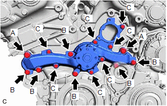
1. INSTALL ENGINE WATER PUMP ASSEMBLY
| (a) Install a new water pump gasket and the engine water pump assembly with the 15 bolts. Torque: Bolt (A) : 43 N·m {438 kgf·cm, 32 ft·lbf} Bolt (B) : 21 N·m {214 kgf·cm, 15 ft·lbf} Bolt (C) : 11 N·m {112 kgf·cm, 8 ft·lbf} Standard Length:
NOTICE:
|
|
2. INSTALL WATER PUMP PULLEY
(a) Temporarily install the water pump pulley with the 4 bolts.
| (b) Using a screwdriver or equivalent with its tip wrapped in protective tape, hold the water pump pulley. |
|
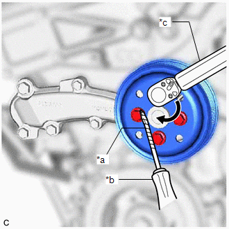
(c) Fully tighten the 4 bolts.
Torque:
21 N·m {214 kgf·cm, 15 ft·lbf}
3. INSTALL NO. 2 IDLER PULLEY SUB-ASSEMBLY
(a) Install the No. 2 idler pulley sub-assembly with the bolt.
Torque:
54 N·m {551 kgf·cm, 40 ft·lbf}
4. INSTALL V-RIBBED BELT
Click here .gif)
5. INSTALL WATER INLET WITH THERMOSTAT SUB-ASSEMBLY
Click here
READ NEXT:
 Components
COMPONENTS ILLUSTRATION *A Type A *B Type B *1 FRONT FLOOR COVER RH - - N*m (kgf*cm, ft.*lbf): Specified torque - - ILLUSTRATION *A Type A *B Type B *1
SEE MORE:
On-vehicle Inspection
ON-VEHICLE INSPECTION PROCEDURE 1. SECURE VEHICLE (a) Fully apply the parking brake and chock a wheel. CAUTION:
Make sure to apply the parking brake and chock a wheel before performing this procedure.
If the vehicle is not secure and the shift lever is moved to N, the vehicle may suddenly move,
Installation
INSTALLATION PROCEDURE 1. INSTALL HYBRID BATTERY TERMINAL BLOCK CAUTION: Be sure to wear insulated gloves and protective goggles. (a) Engage the claw to install the hybrid battery terminal block to the HV battery. (b) Connect the hybrid battery terminal block connector. NOTICE: Make sure that the co
