Lexus ES: Installation
INSTALLATION
CAUTION / NOTICE / HINT
CAUTION:
The engine assembly with transaxle is very heavy. Be sure to follow the procedure described in the repair manual, or the engine lifter may suddenly drop or the engine assembly with transaxle may fall off the engine lifter.
PROCEDURE
1. INSTALL REAR NO. 2 ENGINE MOUNTING BRACKET
HINT:
Perform this procedure only when replacement of the rear No. 2 engine mounting bracket or rear engine mounting bracket is necessary.
(a) Install the rear No. 2 engine mounting bracket to the rear engine mounting bracket with the 2 bolts.
Torque:
42 N·m {428 kgf·cm, 31 ft·lbf}
2. INSTALL TORQUE CONVERTER ASSEMBLY
| (a) Set the key at the top of the front oil pump drive gear and put a matchmark on the transaxle housing. |
|
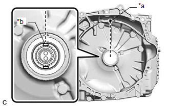
(b) Apply MP grease to place a matchmark on the torque converter assembly so that the position of its groove is clearly indicated.
.png)
| *a | Groove |
| *b | Matchmark |
.png) | MP Grease |
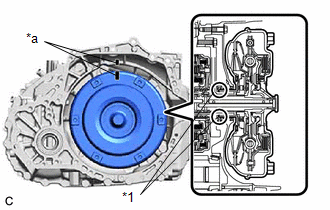
| (c) Align the matchmark on the transaxle housing with the one on the torque converter assembly and engage the splines of the input shaft with the turbine runner splines. NOTICE:
|
|
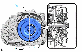
| (d) Rotate the torque converter assembly approximately 180° and engage the splines of the stator shaft with the stator assembly. NOTICE:
|
|
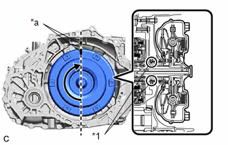
| (e) Rotate the torque converter assembly approximately 180° again, align the matchmark on the torque converter assembly with the one on the housing and insert the groove of the torque converter assembly into the key of the oil pump drive gear. NOTICE:
|
|
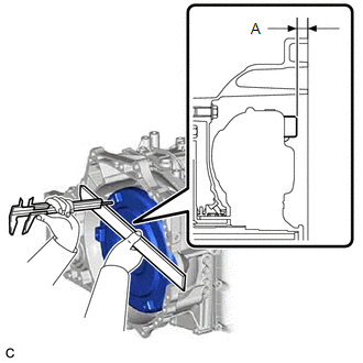
(f) Clean the drive plate and torque converter assembly setting bolt holes.
| (g) Using a vernier caliper and straightedge, measure the dimension (A) shown in the illustration and check the dimension (A). Standard: 14.3 mm (0.563 in.) or more NOTICE:
|
|
3. INSTALL TRANSFER AND TRANSAXLE SETTING STUD BOLT
(a) Clean and degrease the installation holes of the transfer and transaxle setting stud bolt.
(b) Using 2 nuts, install a new transfer and transaxle setting stud bolt to the transaxle housing position shown in the illustration.
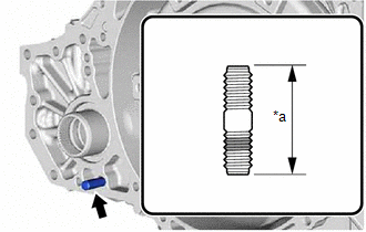
| *a | 53 mm (2.09 in.) |
.png) | Sealant |
Torque:
39.2 N·m {400 kgf·cm, 29 ft·lbf}
NOTICE:
Install the sealed side of the transfer and transaxle setting stud bolt to the transaxle housing.
(c) Using 2 nuts, install 3 new transfer and transaxle setting stud bolts to the transaxle housing at the positions shown in the illustration.
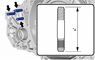
| *a | 73 mm (2.87 in.) |
| | Sealant |
Torque:
39.2 N·m {400 kgf·cm, 29 ft·lbf}
NOTICE:
Install the sealed side of the transfer and transaxle setting stud bolt to the transaxle housing.
4. INSTALL TRANSFER ASSEMBLY
Click here .gif)
5. INSTALL TRANSMISSION VIBRATION CONTROL RUBBER
(a) Clean the installation surface of the 2 transmission vibration control rubbers of the transmission case side cover.
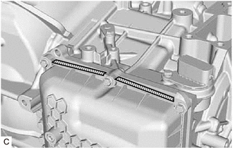
 | Area to be cleaned |
NOTICE:
Completely remove any oil or grease from the contact surfaces of the transmission case side cover.
(b) Install 2 new transmission vibration control rubbers to the transmission case side cover.

| *a | Protrusion (A) |
| *b | Protrusion (B) |
| *c | Protrusion (C) |
| *d | Protrusion (D) |
| | Installation Position |
NOTICE:
- When installing a transmission vibration control rubber, ensure that it will not protrude from the transmission case side cover by aligning it with the edge of protrusion (A) and protrusion (B) or protrusion (C) and protrusion (D) as shown in the illustration.
- Press the entire transmission vibration control rubber by hand to ensure that it is securely installed.
6. INSTALL WIRE HARNESS CLAMP BRACKET
(a) Install the 4 wire harness clamp brackets to the automatic transaxle case sub-assembly and transmission case side cover with the 4 bolts.
Torque:
10 N·m {102 kgf·cm, 7 ft·lbf}
(b) Install the wire harness clamp bracket to the automatic transaxle case sub-assembly with the bolt.
Torque:
19 N·m {194 kgf·cm, 14 ft·lbf}
(c) Install the wire harness clamp bracket to the automatic transaxle case sub-assembly with the bolt.
Torque:
20 N·m {204 kgf·cm, 15 ft·lbf}
7. INSTALL TRANSMISSION CASE PLUG ASSEMBLY
(a) Coat the O-ring of a new transmission case plug assembly with Toyota Genuine ATF WS.
(b) Install the transmission case plug assembly to the transaxle housing.
8. INSTALL NO. 1 TRANSMISSION CONTROL CABLE BRACKET
(a) Install the No. 1 transmission control cable bracket to the automatic transaxle case sub-assembly with the 2 bolts.
Torque:
12 N·m {122 kgf·cm, 9 ft·lbf}
9. INSTALL TRANSMISSION OIL COOLER
Click here
10. INSTALL NO. 1 OIL COOLER TUBE SUB-ASSEMBLY WITHOUT HOSE
Click here
11. CONNECT INLET NO. 1 OIL COOLER HOSE
Click here
12. CONNECT OUTLET NO. 1 OIL COOLER HOSE
Click here
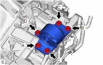
13. INSTALL REAR ENGINE MOUNTING BRACKET SUB-ASSEMBLY
| (a) Install the rear engine mounting bracket sub-assembly to the transaxle housing with the 4 bolts. Torque: 42 N·m {428 kgf·cm, 31 ft·lbf} HINT: Tightening order: Temporarily tighten bolt (A) → Fully tighten bolt (B) → Fully tighten bolt (A) → Fully tighten bolt (C) |
|
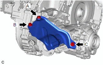
14. INSTALL PROPELLER SHAFT HEAT INSULATOR
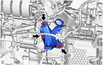
| (a) Install the propeller shaft heat insulator to the rear No. 2 engine mounting bracket and transfer assembly with the 3 bolts. Torque: 18 N·m {184 kgf·cm, 13 ft·lbf} HINT: Tightening order: Temporarily tighten bolt (A) → Temporarily tighten bolt (B) → Fully tighten bolt (C) → Fully tighten bolt (B) → Fully tighten bolt (A) |
|
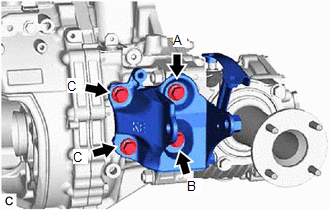
15. INSTALL REAR NO. 2 ENGINE MOUNTING INSULATOR
| (a) Install the rear No. 2 engine mounting insulator to the automatic transaxle case sub-assembly with the 5 bolts. Torque: 42 N·m {428 kgf·cm, 31 ft·lbf} HINT: Tightening order: Temporarily tighten bolt (A) → Fully tighten bolt (B) → Fully tighten bolt (C) → Fully tighten bolt (A) → Fully tighten bolt (D) |
|
16. INSTALL AUTOMATIC TRANSAXLE ASSEMBLY
(a) Apply clutch spline grease to the surface of the crankshaft that contacts the torque converter assembly centerpiece.
Clutch Spline Grease:
Toyota Genuine Clutch Spline Grease or equivalent
Maximum Grease Amount:
Approximately 1 g (0.0353 oz)
.png)
| *1 | Crankshaft |
| *2 | Torque Converter Assembly Centerpiece |
| | Clutch Spline Grease |
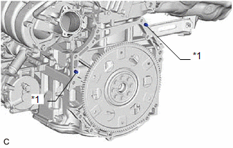
| (b) Confirm that the 2 knock pins are installed on the engine assembly and are not damaged. |
|
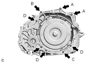
| (c) While keeping the engine assembly and automatic transaxle assembly horizontal, align the knock pins with the holes in the automatic transaxle assembly and install the automatic transaxle assembly with the 8 bolts shown in the illustration. Torque: Bolt (A) : 64 N·m {653 kgf·cm, 47 ft·lbf} Bolt (B) : 46 N·m {469 kgf·cm, 34 ft·lbf} Bolt (C) : 25 N·m {255 kgf·cm, 18 ft·lbf} Bolt (D) : 46 N·m {469 kgf·cm, 34 ft·lbf} Bolt Length:
NOTICE:
|
|
17. INSTALL STARTER ASSEMBLY
Click here
18. INSTALL FLYWHEEL HOUSING SIDE COVER
Click here
19. INSTALL FRONT ENGINE MOUNTING BRACKET
| (a) Install the front engine mounting bracket to the transaxle housing with the 3 bolts. Torque: 42 N·m {428 kgf·cm, 31 ft·lbf} HINT: Tightening order: Temporarily tighten bolt (A) → Fully tighten bolt (B) → Fully tighten bolt (C) → Fully tighten bolt (A) |
|
20. INSTALL FRONT FRAME ASSEMBLY
Click here
21. CONNECT WIRE HARNESS
(a) Engage the wire harness clamp to connect the wire harness to the automatic transaxle assembly.
(b) Install the 2 bolts.
Torque:
10 N·m {102 kgf·cm, 7 ft·lbf}
(c) Engage the 9 wire harness clamps to connect the wire harness.
(d) Install the bolt.
Torque:
10 N·m {102 kgf·cm, 7 ft·lbf}
(e) Connect the wire harness to the rack and pinion power steering gear assembly with the 2 bolts.
Torque:
10 N·m {102 kgf·cm, 7 ft·lbf}
(f) Connect the rack and pinion power steering gear assembly connector.
NOTICE:
Make sure that the connector is fully inserted before rotating the lock lever to engage the lock.
(g) Engage the wire harness clamp and connect the vacuum switching valve (for active control engine mount system) connector.
(h) Connect the park/neutral position switch assembly connector.
| (i) Connect the transmission wire connector and rotate the lever and engage the claw. HINT: Rotate the lever until the claw of the transmission wire connector makes a click sound. |
|
22. INSTALL STEERING GEAR HEAT INSULATOR
Click here
23. INSTALL BREATHER PLUG HOSE
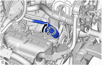
(a) Install the breather plug sub-assembly to the breather plug hose.
(b) Install the breather plug hose to the No. 1 breather plug (ATM).
(c) Engage the hose clamp to connect the breather plug hose.
24. CONNECT WATER BY-PASS HOSE ASSEMBLY
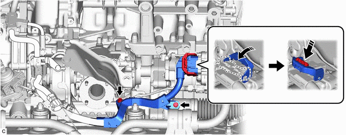
(a) Connect the water by-pass hose assembly to the transmission oil cooler and slide the clip to secure it.
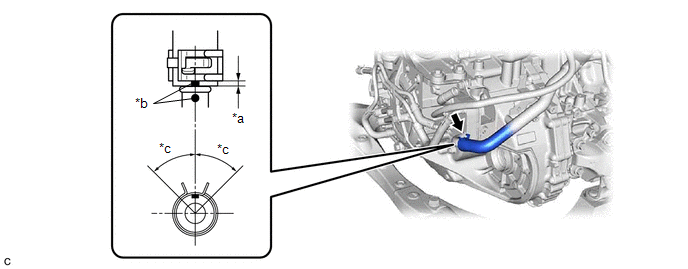
| *a | 2 to 7 mm (0.0787 to 0.276 in.) | *b | Paint Mark |
| *c | 45° (Claw of Clip Location) | - | - |
NOTICE:
- Make sure to slide the water by-pass hose assembly until it contacts the hose stopper of the transmission oil cooler.
- Make sure to align the paint mark of the water by-pass hose assembly with the paint mark of the transmission oil cooler.
- Make sure that the claws of the clip are within the location shown in the illustration.
25. INSTALL FLOW SHUTTING VALVE (NO. 1 WATER BY-PASS HOSE)
Click here
26. CONNECT VACUUM HOSE
(a) Engage the 5 clamps to connect the vacuum hose to the automatic transaxle assembly.
(b) Connect the vacuum hose to the vacuum hose connector.
27. INSTALL DRIVE PLATE AND TORQUE CONVERTER ASSEMBLY SETTING BOLT
(a) Remove any remaining adhesive from the 6 drive plate and torque converter assembly setting bolts.
| (b) Apply a few drops of adhesive to 2 or 3 threads at the tip of each of the 6 drive plate and torque converter assembly setting bolts. Adhesive: Toyota Genuine Adhesive 1324, Three Bond 1324 or equivalent NOTICE: Make sure to install the 6 drive plate and torque converter assembly setting bolts immediately after applying adhesive to prevent foreign matter from attaching to them. |
|
.png)
(c) Turn the crankshaft to gain access to the installation locations of the 6 drive plate and torque converter assembly setting bolts and install each drive plate and torque converter assembly setting bolt while holding the crankshaft pulley bolt with a wrench.
Torque:
41 N·m {418 kgf·cm, 30 ft·lbf}
NOTICE:
First install the black colored drive plate and torque converter assembly setting bolt, and then the remaining 5 silver colored drive plate and torque converter assembly setting bolts.
28. INSTALL FLYWHEEL HOUSING UNDER COVER
Click here
29. INSTALL ENGINE ASSEMBLY WITH TRANSAXLE
Click here
30. CHECK AUTOMATIC TRANSAXLE SYSTEM
NOTICE:
If automatic transaxle parts have been replaced, refer to Parts Replacement Compensation Table to determine if any additional operations are necessary.
Click here
READ NEXT:
 Adjustment
ADJUSTMENT CAUTION / NOTICE / HINT The necessary procedures (adjustment, calibration, initialization or registration) that must be performed after parts are removed and installed, or replaced during a
Components
COMPONENTS ILLUSTRATION *1 NO. 1 ENGINE UNDER COVER *2 NO. 2 ENGINE UNDER COVER ASSEMBLY *3 FRONT WHEEL OPENING EXTENSION PAD LH *4 FRONT WHEEL OPENING EXTENSION PAD RH *5 FR
SEE MORE:
Problem Symptoms Table
PROBLEM SYMPTOMS TABLE NOTICE:
The following inspection procedure of the panoramic view monitor system is described on the assumption that the audio and visual system*1 or navigation system*2 is normal. If the audio and visual system*1 or navigation system*2 has any malfunction, first proceed wit
Dtc Check / Clear
DTC CHECK / CLEAR CHECK FOR DTC (a) Turn the engine switch off. (b) Connect the Techstream to the DLC3. (c) Turn the engine switch on (IG). (d) Turn the Techstream on. (e) Enter the following menus: Chassis / Air suspension / Trouble Codes. Chassis > Air suspension > Trouble Codes HINT: When f
