Lexus ES: Inspection
INSPECTION
PROCEDURE
1. INSPECT POWER WINDOW REGULATOR MOTOR ASSEMBLY (FOR DRIVER DOOR)
| (a) Connect a positive (+) lead from the auxiliary battery to connector terminal 2. NOTICE: Do not connect a positive (+) lead from the auxiliary battery to any terminal other than terminal 2 to avoid damaging the pulse sensor inside the motor. |
|
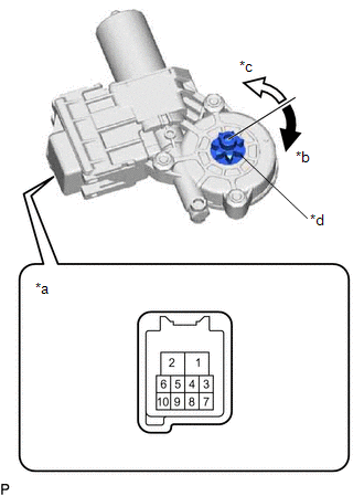
(b) Connect a negative (-) lead from the auxiliary battery to connector terminals 1 and 7 or 10.
(c) Check that the motor gear rotates smoothly as follows:
OK:
| Measurement Condition | Specified Condition |
|---|---|
| Motor gear rotates clockwise |
| Motor gear rotates counterclockwise |
- If the result is not as specified, replace the power window regulator motor assembly (for driver door).
CAUTION:
Initialize the power window control system after installing the front door window regulator assembly.
2. INSPECT POWER WINDOW REGULATOR MOTOR ASSEMBLY (FOR FRONT PASSENGER DOOR)
| (a) Connect a positive (+) lead from the auxiliary battery to connector terminal 2. NOTICE: Do not connect a positive (+) lead from the auxiliary battery to any terminal other than terminal 2 to avoid damaging the pulse sensor inside the motor. |
|
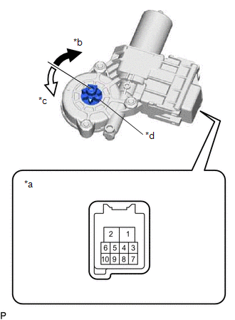
(b) Connect a negative (-) lead from the auxiliary battery to connector terminals 1 and 7 or 10.
(c) Check that the motor gear rotates smoothly as follows:
OK:
| Measurement Condition | Specified Condition |
|---|---|
| Motor gear rotates counterclockwise |
| Motor gear rotates clockwise |
- If the result is not as specified, replace the power window regulator motor assembly (for front passenger door).
CAUTION:
Initialize the power window control system after installing the front door window regulator assembly.
READ NEXT:
 Installation
INSTALLATION CAUTION / NOTICE / HINT HINT:
Use the same procedure for the RH side and LH side.
The following procedure is for the LH side.
PROCEDURE 1. PRECAUTION NOTICE: After turning the eng
Components
COMPONENTS ILLUSTRATION *1 COURTESY LIGHT ASSEMBLY *2 REAR DOOR TRIM BOARD SUB-ASSEMBLY *3 REAR DOOR TRIM UPPER PAD *4 REAR POWER WINDOW REGULATOR SWITCH ASSEMBLY WITH REAR DOOR UP
SEE MORE:
Screen Flicker or Color Distortion
PROCEDURE 1. CHECK DISPLAY SETTING (a) Reset display settings (contrast, brightness) and check that the screen appears normal. OK: The display returns to normal. OK END (DISPLAY SETTING WAS CAUSE OF MALFUNCTION) NG PROCEED TO NEXT SUSPECTED AREA SHOWN IN PROBLEM SYMPTOMS TA
Microphone Circuit Open (B157213)
DESCRIPTION This DTC is stored when the DCM (telematics transceiver) detects a malfunction in the telephone microphone assembly circuit. DTC No. Detection Item DTC Detection Condition Trouble Area B157213 Microphone Circuit Open Current at terminal MCVD is lower than the malfunction
