Lexus ES: Inspection
INSPECTION
PROCEDURE
1. INSPECT STEERING PAD SWITCH ASSEMBLY
(a) Measure the resistance according to the value(s) in the table below.
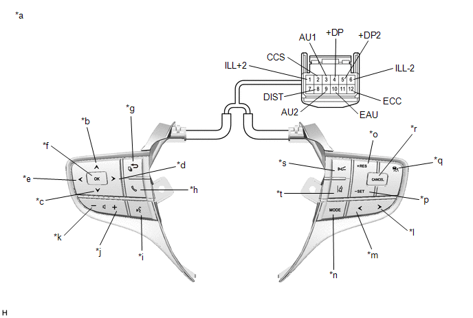
| *a | Component without harness connected (Steering Pad Switch Assembly) | *b | Up |
| *c | Down | *d | Right |
| *e | Left | *f | OK |
| *g | Back | *h | On/off Hook |
| *i | Voice | *j | Volume+ |
| *k | Volume- | *l | Seek+ |
| *m | Seek- | *n | MODE |
| *o | +RES | *p | -SET |
| *q | Cruise Control Main | *r | CANCEL |
| *s | Distance Control | *t | Lane Departure Alert |
Standard Resistance:
| Tester Connection | Condition | Specified Condition |
|---|---|---|
| 3 (AU1) - 10 (EAU) | No switch pushed | 95 to 105 kΩ |
| Seek+ switch pushed | Below 2.5 Ω | |
| Seek- switch pushed | 313 to 345 Ω | |
| Volume+ switch pushed | 950 to 1050 Ω | |
| Volume- switch pushed | 2955 to 3265 Ω | |
| 9 (AU2) - 10 (EAU) | No switch pushed | 95 to 105 kΩ |
| MODE switch pushed | Below 2.5 Ω | |
| On/off hook switch pushed | 950 to 1050 Ω | |
| Voice switch pushed | 2955 to 3265 Ω | |
| 5 (+DP2) - 10 (EAU) | No switch pushed | 95 to 105 kΩ |
| Left switch pushed | Below 2.5 Ω | |
| Up switch pushed | 313 to 345 Ω | |
| Down switch pushed | 950 to 1050 Ω | |
| Right switch pushed | 2955 to 3265 Ω | |
| 4 (+DP) - 10 (EAU) | No switch pushed | 95 to 105 kΩ |
| OK switch pushed | Below 2.5 Ω | |
| Back switch pushed | 313 to 345 Ω | |
| 8 (DIST) - 12 (ECC) | No switch pushed | 1 MΩ or higher |
| Distance control switch pushed | Below 2.5 Ω | |
| Lane departure alert switch pushed | 228 to 252 Ω | |
| 2 (CCS) - 12 (ECC) | No switch pushed | 1 MΩ or higher |
| Cruise control main switch pushed | Below 2.5 Ω | |
| CANCEL switch pushed | 228 to 252 Ω | |
| +RES switch pushed | 599 to 661 Ω | |
| -SET switch pushed | 1463 to 1617 Ω |
HINT:
If the result is not as specified, replace the steering pad switch assembly.
(b) Check the illumination.
(1) Connect a positive (+) lead from the auxiliary battery to terminal 1 (ILL+2) and a negative (-) lead to terminal 6 (ILL-2) of the steering pad switch assembly connector.
(2) Check that the steering pad switch assembly illumination illuminates.
OK:
The steering pad switch assembly illumination illuminates.
HINT:
If the result is not as specified, replace the steering pad switch assembly.
READ NEXT:
 Removal
REMOVAL CAUTION / NOTICE / HINT The necessary procedures (adjustment, calibration, initialization or registration) that must be performed after parts are removed and installed, or replaced during stee
Precaution
PRECAUTION HANDLING PRECAUTIONS FOR STEERING SYSTEM (a) Care must be taken when replacing parts. Incorrect replacement may affect the performance of the steering system and result in a driving hazard.
SEE MORE:
Telephone Main Antenna Circuit Short to Ground (B15CB11,B15CB13)
DESCRIPTION This DTC is stored when the DCM (telematics transceiver) detects an open or a short in the telephone antenna (main) circuit. DTC No. Detection Item DTC Detection Condition Trouble Area B15CB11 Telephone Main Antenna Circuit Short to Ground Telephone antenna (main) impeda
Lost Communication with Wiper System LIN BUS (B1373)
DESCRIPTION The main body ECU (multiplex network body ECU) and windshield wiper motor assembly communicate via LIN communication. The main body ECU (multiplex network body ECU) stores this DTC if communication becomes abnormal. DTC No. Detection Item DTC Detection Condition Trouble Area M
