Lexus ES: Fuel Lid Opener does not Operate
DESCRIPTION
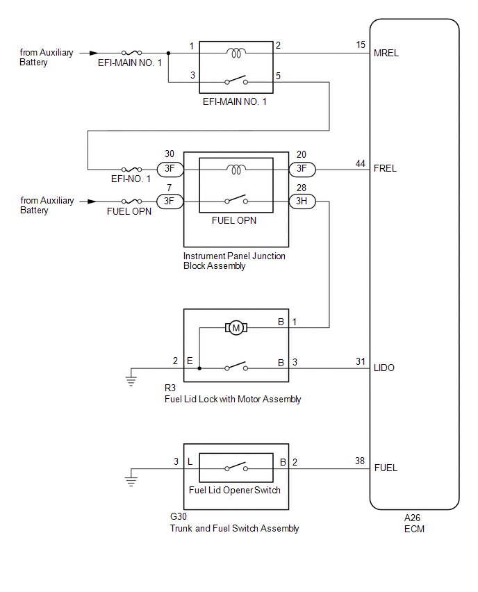
When the trunk and fuel switch assembly (fuel lid opener switch) is pushed, a trunk and fuel switch assembly (fuel lid opener switch) signal is sent to the ECM. The ECM turns on the FUEL OPN relay and EFI-MAIN NO. 1 relay, and the fuel lid lock with motor assembly opens the fuel lid. When the fuel lid is open, a fuel lid courtesy switch signal is output from the fuel lid lock with motor assembly.
WIRING DIAGRAM
CAUTION / NOTICE / HINT
NOTICE:
Inspect the fuses for circuits related to this system before performing the following procedure.
PROCEDURE
| 1. | CHECK FOR DTCs (HEALTH CHECK) |
(a) Connect the Techstream to the DLC3.
(b) Turn the power switch on (IG).
(c) Turn the Techstream on.
(d) Enter the following menus: System Select / Health Check.
(e) Check DTCs.
| Result | Proceed to |
|---|---|
| No DTCs are output. | A |
| DTCs are output. | B |
| B | .gif) | GO TO DTC CHART |
|
.gif)
| 2. | CHECK EVAPORATIVE EMISSION CONTROL SYSTEM |
(a) Perform the Evaporative System Check using the Techstream (Automatic Mode). Refer to "CONFIRMATION DRIVING PATTERN" of P045011.
Click here .gif)
(b) Check for DTCs.
Powertrain > Engine > Trouble CodesOK:
Evaporative emission control system DTCs are not output.
| NG | | GO TO SFI SYSTEM |
|
| 3. | PERFORM ACTIVE TEST USING TECHSTREAM (ACTIVATE THE FUEL FILLER OPENER) |
(a) Enter the following menus: Powertrain / Engine / Active Test.
(b) Perform the Active Test according to the display on the Techstream.
Powertrain > Engine > Active Test| Tester Display | Measurement Item | Control Range | Diagnostic Note |
|---|---|---|---|
| Activate the Fuel Filler Opener | Fuel lid lock with motor assembly | OFF/ON | - |
| Tester Display |
|---|
| Activate the Fuel Filler Opener |
OK:
The fuel lid lock with motor assembly operates normally.
| NG | | GO TO STEP 10 |
|
| 4. | READ VALUE USING TECHSTREAM (FUEL LID SW) |
(a) Enter the following menus: Powertrain / Engine / Data List.
(b) Read the Data List according to the display on the Techstream.
Powertrain > Engine > Data List| Tester Display | Measurement Item | Range | Normal Condition | Diagnostic Note |
|---|---|---|---|---|
| Fuel Lid SW | Fuel lid opener switch status | Close or Open | Close: Trunk and fuel switch assembly (fuel lid opener switch) not pushed Open: Trunk and fuel switch assembly (fuel lid opener switch) pushed | - |
| Tester Display |
|---|
| Fuel Lid SW |
OK:
The Techstream display changes correctly in response to the operation of the trunk and fuel switch assembly (fuel lid opener switch).
| NG | | GO TO STEP 8 |
|
| 5. | READ VALUE USING TECHSTREAM (FUEL LID SENSOR SW) |
(a) Enter the following menus: Powertrain / Engine / Data List.
(b) Read the Data List according to the display on the Techstream.
Powertrain > Engine > Data List| Tester Display | Measurement Item | Range | Normal Condition | Diagnostic Note |
|---|---|---|---|---|
| Fuel Lid Sensor SW | Fuel lid courtesy switch status | Close or Open | Close: Fuel lid closed Open: Fuel lid open | - |
| Tester Display |
|---|
| Fuel Lid Sensor SW |
OK:
The Techstream display changes correctly in response to the operation of the fuel lid courtesy switch (fuel lid lock with motor assembly).
| OK | | REPLACE ECM |
|
| 6. | INSPECT FUEL LID LOCK WITH MOTOR ASSEMBLY (FUEL LID COURTESY SWITCH) |
(a) Remove the fuel lid lock with motor assembly.
Click here
(b) Inspect the fuel lid lock with motor assembly (fuel lid courtesy switch).
Click here
| NG | | REPLACE FUEL LID LOCK WITH MOTOR ASSEMBLY |
|
| 7. | CHECK HARNESS AND CONNECTOR (FUEL LID LOCK WITH MOTOR ASSEMBLY - ECM) |
(a) Disconnect the A26 ECM connector.
(b) Measure the resistance according to the value(s) in the table below.
Standard Resistance:
| Tester Connection | Condition | Specified Condition |
|---|---|---|
| R3-3 (B) - A26-31 (LIDO) | Always | Below 1 Ω |
| R3-3 (B) or A26-31 (LIDO) - Body ground | Always | 10 kΩ or higher |
| OK | | REPLACE ECM |
| NG | | REPAIR OR REPLACE HARNESS OR CONNECTOR |
| 8. | INSPECT TRUNK AND FUEL SWITCH ASSEMBLY (FUEL LID OPENER SWITCH) |
(a) Remove the trunk and fuel switch assembly (fuel lid opener switch).
Click here
(b) Inspect the trunk and fuel switch assembly (fuel lid opener switch).
Click here
| NG | | REPLACE TRUNK AND FUEL SWITCH ASSEMBLY (FUEL LID OPENER SWITCH) |
|
| 9. | CHECK HARNESS AND CONNECTOR (TRUNK AND FUEL SWITCH ASSEMBLY (FUEL LID OPENER SWITCH) - ECM AND BODY GROUND) |
(a) Disconnect the A26 ECM connector.
(b) Measure the resistance according to the value(s) in the table below.
Standard Resistance:
| Tester Connection | Condition | Specified Condition |
|---|---|---|
| G30-2 (B) - A26-38 (FUEL) | Always | Below 1 Ω |
| G30-3 (L) - Body ground | Always | Below 1 Ω |
| G30-2 (B) or A26-38 (FUEL) - Body ground | Always | 10 kΩ or higher |
| OK | | REPLACE ECM |
| NG | | REPAIR OR REPLACE HARNESS OR CONNECTOR |
| 10. | INSPECT FUEL LID LOCK WITH MOTOR ASSEMBLY |
(a) Remove the fuel lid lock with motor assembly.
Click here
(b) Inspect the fuel lid lock with motor assembly (motor operation).
Click here
| NG | | REPLACE FUEL LID LOCK WITH MOTOR ASSEMBLY |
|
| 11. | CHECK HARNESS AND CONNECTOR (INSTRUMENT PANEL JUNCTION BLOCK ASSEMBLY - EFI-MAIN RELAY AND AUXILIARY BATTERY) |
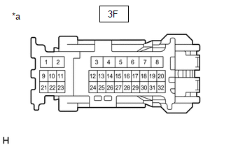
(a) Disconnect the 3F instrument panel junction block assembly connector.
| (b) Measure the voltage according to the value(s) in the table below. Standard Voltage:
|
|
| Result | Proceed to |
|---|---|
| OK | A |
| The result for terminal 3F-7 is not as specified. | B |
| The result for terminal 3F-30 (with power switch on (IG)) is not as specified. | |
| The result for terminal 3F-30 (with power switch off and trunk and fuel switch assembly (fuel lid opener switch) pressed) is not as specified. | C |
| B | | REPAIR OR REPLACE HARNESS OR CONNECTOR |
| C | | REPLACE ECM |
|
| 12. | CHECK HARNESS AND CONNECTOR (INSTRUMENT PANEL JUNCTION BLOCK ASSEMBLY - ECM) |
(a) Disconnect the A26 ECM connector.
(b) Measure the resistance according to the value(s) in the table below.
Standard Resistance:
| Tester Connection | Condition | Specified Condition |
|---|---|---|
| 3F-20 - A26-44 (FREL) | Always | Below 1 Ω |
| 3F-20 or A26-44 (FREL) - Body ground | Always | 10 kΩ or higher |
| NG | | REPAIR OR REPLACE HARNESS OR CONNECTOR |
|
| 13. | CHECK HARNESS AND CONNECTOR (INSTRUMENT PANEL JUNCTION BLOCK ASSEMBLY - FUEL LID LOCK WITH MOTOR ASSEMBLY) |
(a) Disconnect the 3H instrument panel junction block assembly connector.
(b) Measure the resistance according to the value(s) in the table below.
Standard Resistance:
| Tester Connection | Condition | Specified Condition |
|---|---|---|
| 3H-28 - R3-1 (B) | Always | Below 1 Ω |
| 3H-28 or R3-1 (B) - Body ground | Always | 10 kΩ or higher |
| NG | | REPAIR OR REPLACE HARNESS OR CONNECTOR |
|
| 14. | REPLACE INSTRUMENT PANEL JUNCTION BLOCK ASSEMBLY |
(a) Replace the instrument panel junction block assembly.
Click here
|
| 15. | CHECK FUEL LID OPEN OPERATION |
(a) Check that the fuel lid can be opened.
Click here
OK:
The fuel lid can be opened.
| OK | | END (INSTRUMENT PANEL JUNCTION BLOCK ASSEMBLY WAS DEFECTIVE) |
| NG | | REPLACE ECM |
READ NEXT:
 Components
COMPONENTS ILLUSTRATION *A for TMK Made *B for TMMK Made *1 HOOD CUSHION CENTER *2 HOOD INSULATOR *3 WASHER HOSE ASSEMBLY *4 WASHER NOZZLE SUB-ASSEMBLY *5 HOOD INSU
On-vehicle Inspection
ON-VEHICLE INSPECTION PROCEDURE 1. INSPECT HOOD SUB-ASSEMBLY (a) Check that the clearance measurements of areas a through d are within each standard range. Standard Clearance Area Measurement
SEE MORE:
Thermostat Heater Control Circuit Short to Ground or Open (P059714)
DESCRIPTION Refer to DTC P059712. Click here DTC No. Detection Item DTC Detection Condition Trouble Area MIL Memory Note P059714 Thermostat Heater Control Circuit Short to Ground or Open Open or short in thermostat heater circuit and power supply circuit (1 trip detection lo
Steering Angle Sensor (C1A47)
DESCRIPTION The blind spot monitor sensor receives steering angle signals from the steering sensor via CAN communication. Blind Spot Monitor Master DTC No. Detection Item DTC Detection Condition Trouble Area C1A47 Steering Angle Sensor A fail flag is transmitted from the steering an
