Lexus ES: Inspection
INSPECTION
PROCEDURE
1. INSPECT FRONT OIL PUMP ASSEMBLY
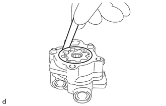
| (a) Install the oil pump drive shaft sub-assembly to the front oil pump assembly. NOTICE:
|
|
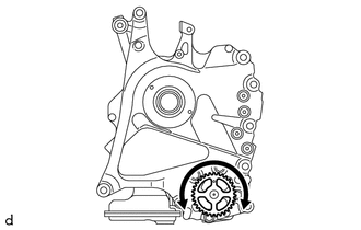
(b) Make sure that the oil pump drive shaft sub-assembly rotates smoothly.
If the oil pump drive shaft sub-assembly does not rotate smoothly, inspect the front oil pump drive gear and front oil pump driven gear and front oil pump body.
(c) Remove the oil pump drive shaft sub-assembly from the front oil pump assembly.
NOTICE:
To avoid damaging the bush of the front oil pump assembly, remove the oil pump drive shaft sub-assembly perpendicularly relative to the front oil pump assembly.
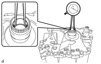
2. INSPECT STATOR SHAFT ASSEMBLY
| (a) Using a caliper gauge, measure the inside diameter of the bushing of the stator shaft assembly (for torque converter assembly). Standard Inside Diameter: 25.201 to 25.227 mm (0.992 to 0.993 in.) Maximum Inside Diameter: 25.227 mm (0.993 in.) If the inside diameter is more than the maximum, replace the stator shaft assembly. |
|
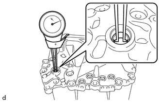
| (b) Using a caliper gauge, measure the inside diameter of the bushing of the stator shaft assembly (for oil pump drive shaft sub-assembly). Standard Inside Diameter: 12.020 to 12.035 mm (0.473 to 0.474 in.) Maximum Inside Diameter: 12.035 mm (0.474 in.) If the inside diameter is more than the maximum, replace the stator shaft assembly. |
|
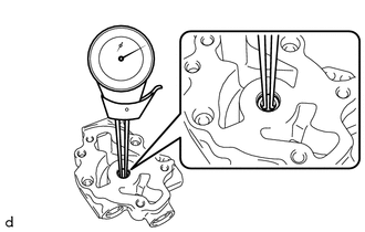
3. INSPECT FRONT OIL PUMP COVER SUB-ASSEMBLY
| (a) Using a caliper gauge, measure the inside diameter of the bushing of the front oil pump cover sub-assembly. Standard Inside Diameter: 8.02 to 8.035 mm (0.31575 to 0.31634 in.) Maximum Inside Diameter: 8.035 mm (0.31634 in.) If the inside diameter is more than the maximum, replace the front oil pump cover sub-assembly. |
|
4. INSPECT FRONT OIL PUMP BODY AND GEAR SUB-ASSEMBLY
| (a) Using a feeler gauge, measure the body clearance between the front oil pump driven gear and front oil pump body. Standard Body Clearance: 0.135 to 0.175 mm (0.00531 to 0.00689 in.) Maximum Body Clearance: 0.175 mm (0.00689 in.) If the body clearance is more than the maximum, replace the front oil pump body and front oil pump driven gear. |
|
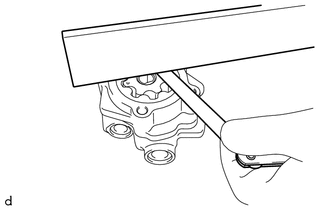
| (b) Using a straightedge and feeler gauge, measure the side clearance of both gears. Standard Side Clearance: 0.015 to 0.034 mm (0.000591 to 0.00134 in.) Maximum Side Clearance: 0.034 mm (0.00134 in.) If the side clearance is more than the maximum, replace the front oil pump body, front oil pump drive gear, front oil pump driven gear and stator shaft assembly. |
|
READ NEXT:
 Reassembly
REASSEMBLY PROCEDURE 1. INSTALL RING PIN (a) Install the 2 ring pins to the front oil pump cover sub-assembly. 2. INSTALL FRONT OIL PUMP BODY (a) Install the front oil pump body to t
Adjustment
ADJUSTMENT CAUTION / NOTICE / HINT The necessary procedures (adjustment, calibration, initialization or registration) that must be performed after parts are removed and installed, or replaced during p
SEE MORE:
Removal
REMOVAL CAUTION / NOTICE / HINT The necessary procedures (adjustment, calibration, initialization, or registration) that must be performed after parts are removed and installed, or replaced during luggage door opening cancel switch assembly removal/installation are shown below. Necessary Procedure A
On-vehicle Inspection
ON-VEHICLE INSPECTION CAUTION / NOTICE / HINT CAUTION: To prevent injury due to contact with an operating cooling fan, keep your hands and clothing away from the cooling fans when working in the engine compartment with the engine running or the power switch on (IG). PROCEDURE 1. VISUALLY CHECK HOSE
