Lexus ES: GPS Antenna Connection Malfunction(short) (B15C0,B15C1)
DESCRIPTION
These DTCs are stored when a malfunction occurs in the navigation antenna assembly.
| DTC No. | Detection Item | DTC Detection Condition | Trouble Area |
|---|---|---|---|
| B15C0 | GPS Antenna Connection Malfunction(short) | GPS Antenna Connection Malfunction(short) |
|
| B15C1 | GPS Antenna Connection Malfunction(break) | GPS Antenna Connection Malfunction(break) |
|
WIRING DIAGRAM
CAUTION / NOTICE / HINT
NOTICE:
-
Depending on the parts that are replaced during vehicle inspection or maintenance, performing initialization, registration or calibration may be needed. Refer to Precaution for Audio and Visual System.
Click here
.gif)
-
When replacing the radio receiver assembly, always replace it with a new one. If a radio receiver assembly which was installed to another vehicle is used, the following may occur:
- A communication malfunction DTC may be stored.
- The radio receiver assembly may not operate normally.
PROCEDURE
| 1. | CHECK DTC |
(a) Clear the DTCs.
Body Electrical > Navigation System > Clear DTCs(b) Recheck for DTCs and check that no DTCs are output.
Body Electrical > Navigation System > Trouble CodesOK:
No DTCs are output.
| OK | .gif) | USE SIMULATION METHOD TO CHECK |
|
.gif)
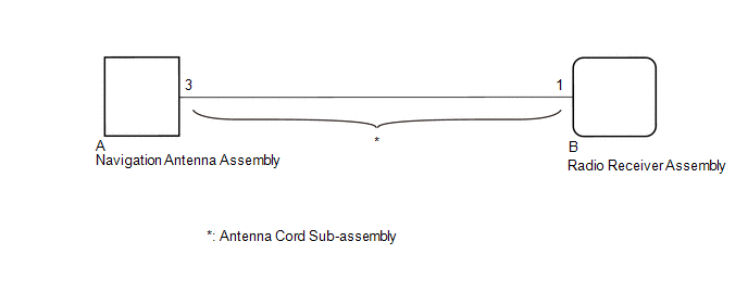
| 2. | INSPECT ANTENNA CORD SUB-ASSEMBLY |
(a) Remove the antenna cord sub-assembly.
Click here
(b) Measure the resistance according to the value(s) in the table below.
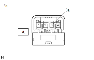
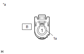
| *a | Component without harness connected (Antenna Cord Sub-assembly) |
| *a | Component without harness connected (Antenna Cord Sub-assembly) |
Standard Resistance:
| Tester Connection | Condition | Specified Condition |
|---|---|---|
| A-3 - B-1 | Always | Below 1 Ω |
| A-3a - B-1a | Always | Below 1 Ω |
| A-3 or B-1 - Body ground | Always | 10 kΩ or higher |
| A-3a or B-1a - Body ground | Always | 10 kΩ or higher |
| NG | | REPLACE ANTENNA CORD SUB-ASSEMBLY |
|
| 3. | INSPECT NAVIGATION ANTENNA ASSEMBLY |
(a) Remove the navigation antenna assembly.
Click here
(b) Inspect the navigation antenna assembly.
Click here
| OK | | REPLACE RADIO RECEIVER ASSEMBLY |
| NG | | REPLACE NAVIGATION ANTENNA ASSEMBLY |
READ NEXT:
 Speaker Output Short (B15C3)
DESCRIPTION This DTC is stored when a malfunction occurs in the speakers. DTC No. Detection Item DTC Detection Condition Trouble Area B15C3 Speaker Output Short A short is detected in
Stereo Component Amplifier Disconnected (B15D3)
DESCRIPTION The radio receiver assembly and stereo component amplifier assembly are connected by AVC-LAN communication lines. This DTC is stored when an AVC-LAN communication error occurs between the
Display Disconnected (B15D6)
DESCRIPTION The multi-display assembly and radio receiver assembly are connected by AVC-LAN communication lines. This DTC is stored when an AVC-LAN communication error occurs between the multi-display
SEE MORE:
"HAVE TRACTION BATTERY INSPECTED" is displayed
DESCRIPTION The battery ECU assembly monitors the SOC (state of charge) of the HV battery. When it finds the HV battery has deteriorated excessively, it will display "Have Traction Battery Inspected" on the multi-information display. If "Have Traction Battery Inspected" is displayed, perform "Batter
Installation
INSTALLATION PROCEDURE 1. INSTALL NAVIGATION ANTENNA BRACKET 2. INSTALL NAVIGATION ANTENNA ASSEMBLY (a) Engage the 6 guides and 2 claws to install the navigation antenna assembly as shown in the illustration. Install in this Direction 3. INSTALL NAVIGATION ANTENNA ASSEMBLY WITH BRACKET (a)
