Lexus ES: GNSS Antenna Circuit Short to Ground (B15C111,B15C113)
DESCRIPTION
These DTCs are stored when a malfunction occurs in the telephone and GPS antenna assembly (for Roof Side) circuit.
| DTC No. | Detection Item | DTC Detection Condition | Trouble Area |
|---|---|---|---|
| B15C111 | GNSS Antenna Circuit Short to Ground | Current to the GNSS antenna is lower than the malfunction threshold for 10 seconds or more when the engine switch is on (IG) (Short circuit) |
|
| B15C113 | GNSS Antenna Circuit Open | Current to the GNSS antenna is higher than the malfunction threshold for 10 seconds or more when the engine switch is on (IG) (Open circuit) |
|
WIRING DIAGRAM
w/ SXM Function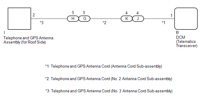 w/o SXM Function
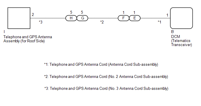
CAUTION / NOTICE / HINT
NOTICE:
Depending on the parts that are replaced during vehicle inspection or maintenance, performing initialization, registration or calibration may be needed. Refer to Precaution for Safety Connect System.
Click here .gif)
PROCEDURE
| 1. | CHECK DTC |
(a) Turn the engine switch off.
(b) Connect the Techstream to the DLC3.
(c) Turn the engine switch on (IG) and wait for 10 seconds or more.
(d) Turn the Techstream on.
(e) Clear the DTCs.
Body Electrical > Telematics > Clear DTCs(f) Check for DTCs and check that no DTCs are output.
Body Electrical > Telematics > Trouble CodesOK:
No DTCs are output.
| OK |  | USE SIMULATION METHOD TO CHECK |
|

| 2. | INSPECT TELEPHONE AND GPS ANTENNA CORD (ANTENNA CORD SUB-ASSEMBLY) |
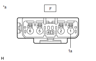
(a) Disconnect the J*1 or E*2 telephone and GPS antenna cord (antenna cord sub-assembly) connector.
w/ SXM Function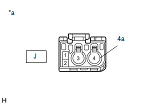
| *a | Component without harness connected (Telephone and GPS Antenna Cord (Antenna Cord Sub-assembly)) |
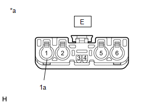
| *a | Component without harness connected (Telephone and GPS Antenna Cord (Antenna Cord Sub-assembly)) |
- *1: w/ SXM Function
- *2: w/o SXM Function
| (b) Disconnect the B telephone and GPS antenna cord (antenna cord sub-assembly) connector. |
|
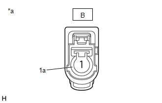
(c) Measure the resistance according to the value(s) in the table below.
Standard Resistance:
w/ SXM Function| Tester Connection | Condition | Specified Condition |
|---|---|---|
| J-4 - B-1 | Always | Below 1 Ω |
| J-4 or B-1 - Body ground | Always | 10 kΩ or higher |
| J-4a - B-1a | Always | Below 1 Ω |
| J-4a or B-1a - Body ground | Always | 10 kΩ or higher |
| Tester Connection | Condition | Specified Condition |
|---|---|---|
| E-1 - B-1 | Always | Below 1 Ω |
| E-1 or B-1 - Body ground | Always | 10 kΩ or higher |
| E-1a - B-1a | Always | Below 1 Ω |
| E-1a or B-1a - Body ground | Always | 10 kΩ or higher |
| NG | | REPLACE TELEPHONE AND GPS ANTENNA CORD (ANTENNA CORD SUB-ASSEMBLY) |
|
| 3. | INSPECT TELEPHONE AND GPS ANTENNA CORD (NO. 2 ANTENNA CORD SUB-ASSEMBLY) |
(a) Disconnect the K*1 or F*2 telephone and GPS antenna cord (No. 2 antenna cord sub-assembly) connector.
w/ SXM Function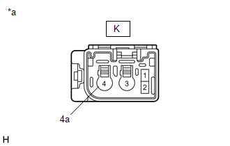
| *a | Component without harness connected (Telephone and GPS Antenna Cord (No. 2 Antenna Cord Sub-assembly)) |
| *a | Component without harness connected (Telephone and GPS Antenna Cord (No. 2 Antenna Cord Sub-assembly)) |
- *1: w/ SXM Function
- *2: w/o SXM Function
| (b) Disconnect the G telephone and GPS antenna cord (No. 2 antenna cord sub-assembly) connector. |
|
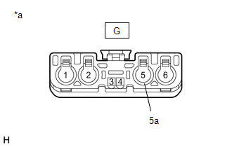
(c) Measure the resistance according to the value(s) in the table below.
Standard Resistance:
w/ SXM Function| Tester Connection | Condition | Specified Condition |
|---|---|---|
| K-4 - G-5 | Always | Below 1 Ω |
| K-4 or G-5 - Body ground | Always | 10 kΩ or higher |
| K-4a - G-5a | Always | Below 1 Ω |
| K-4a or G-5a - Body ground | Always | 10 kΩ or higher |
| Tester Connection | Condition | Specified Condition |
|---|---|---|
| F-1 - G-5 | Always | Below 1 Ω |
| F-1 or G-5 - Body ground | Always | 10 kΩ or higher |
| F-1a - G-5a | Always | Below 1 Ω |
| F-1a or G-5a - Body ground | Always | 10 kΩ or higher |
| NG | | REPLACE TELEPHONE AND GPS ANTENNA CORD (NO. 2 ANTENNA CORD SUB-ASSEMBLY) |
|
| 4. | INSPECT TELEPHONE AND GPS ANTENNA CORD (NO. 3 ANTENNA CORD SUB-ASSEMBLY) |
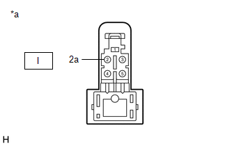
| (a) Disconnect the I telephone and GPS antenna cord (No. 3 antenna cord sub-assembly) connector. |
|
| (b) Disconnect the H telephone and GPS antenna cord (No. 3 antenna cord sub-assembly) connector. |
|
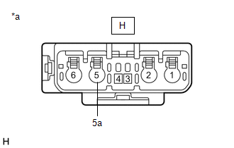
(c) Measure the resistance according to the value(s) in the table below.
Standard Resistance:
| Tester Connection | Condition | Specified Condition |
|---|---|---|
| I-2 - H-5 | Always | Below 1 Ω |
| I-2 or H-5 - Body ground | Always | 10 kΩ or higher |
| I-2a - H-5a | Always | Below 1 Ω |
| I-2a or H-5a - Body ground | Always | 10 kΩ or higher |
| NG | | REPLACE TELEPHONE AND GPS ANTENNA CORD (NO. 3 ANTENNA CORD SUB-ASSEMBLY) |
|
| 5. | REPLACE TELEPHONE AND GPS ANTENNA ASSEMBLY (for Roof Side) |
(a) Replace the telephone and GPS antenna assembly (for Roof Side) with a new or known good one and check if the same problem occurs again.
Click here
OK:
The system returns to normal.
| OK | | END |
|
| 6. | REPLACE DCM (TELEMATICS TRANSCEIVER) |
(a) Replace the DCM (Telematics Transceiver).
Click here
NOTICE:
- The engine switch must be off.
- Do not swap the DCM (Telematics Transceiver) with one from another vehicle.
| NEXT | | PERFORM DCM ACTIVATION |
READ NEXT:
 Airbag Signal Signal Plausibility Failure (B15C464)
DESCRIPTION If the DCM (telematics transceiver) detects an error in communication between the DCM (telematics transceiver) and the airbag ECU assembly as a result of the DCM (telematics transceiver) s
Emergency Call Switch Circuit Short to Ground (B15C511,B15C513)
DESCRIPTION If the DCM (telematics transceiver) detects an error in the communication between the DCM (telematics transceiver) and the map light sub-assembly (manual (SOS) switch) as a result of the D
Telephone Main Antenna Circuit Short to Ground (B15CB11,B15CB13)
DESCRIPTION This DTC is stored when the DCM (telematics transceiver) detects an open or a short in the telephone antenna (main) circuit. DTC No. Detection Item DTC Detection Condition Trouble
SEE MORE:
Installation
INSTALLATION PROCEDURE 1. INSTALL REAR STABILIZER BUSHING (a) Install the 2 rear stabilizer bushings to the outside of the stoppers on the rear stabilizer bar. NOTICE: Be sure to install the rear stabilizer bushings so that each cutout faces the front of the vehicle. HINT: The cutout of the rear
High Voltage Power Resource Circuit Consumption Circuit Short (P1C8149,P1C8249)
DTC SUMMARY MALFUNCTION DESCRIPTION The hybrid vehicle control ECU monitors the high-voltage wiring between the HV battery and inverter with converter assembly and detects a short circuit malfunction or high-voltage system operation malfunction. The cause of this malfunction may be one of the follow
