Lexus ES: VC Output Circuit
DESCRIPTION
The ECM constantly generates a 5 V power source voltage from the battery voltage supplied to the +B, +B2 (BATT) terminals to operate the microprocessor. The ECM also provides this power to the sensors through the VC output circuit.
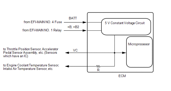
When the VC circuit has a short circuit, the microprocessor in the ECM and sensors that are supplied power through the VC circuit are deactivated because power is not supplied from the VC circuit. When the system is in this condition, it will not start.
WIRING DIAGRAM
-
For the circuit diagram of the ECM power source refer to the ECM power source circuit.
Click here
.gif)
-
VC Output Circuit
CAUTION / NOTICE / HINT
NOTICE:
Check the fuses for circuits related to this system before performing the following inspection procedure.
PROCEDURE
| 1. | CHECK CONNECTION BETWEEN TECHSTREAM AND ECM |
(a) Connect the Techstream to the DLC3.
(b) Turn the engine switch on (IG).
(c) Turn the Techstream on.
(d) Check the communication between the Techstream and ECM.
HINT:
It can be checked using the "Engine" item of the Data List.
| Result | Proceed to |
|---|---|
| Communication is not possible | A |
| Communication is possible | B |
| B | .gif) | PROCEED TO NEXT SUSPECTED AREA SHOWN IN PROBLEM SYMPTOMS TABLE |
|
.gif)
| 2. | CHECK EFI NO. 1 FUSE VOLTAGE |
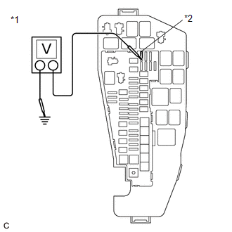
| *1 | No. 1 Engine Room Relay Block and No. 1 Junction Block Assembly |
| *2 | EFI NO. 1 Fuse |
(a) Turn the engine switch on (IG).
(b) Measure the voltage according to the value(s) in the table below.
Standard Voltage:
| Tester Connection | Condition | Specified Condition |
|---|---|---|
| 1 (EFI NO. 1 fuse) - Body ground | Engine switch on (IG) | 11 to 14 V |
HINT:
- Check the fuse with it installed to the No. 1 engine room relay block and No. 1 junction block assembly.
- If the result is not as specified, since current is not flowing to the +B and +B2 terminals of the ECM, the system may not be started.
| NG | | GO TO ECM POWER SOURCE CIRCUIT |
|
| 3. | CHECK CONNECTION BETWEEN TECHSTREAM AND ECM (THROTTLE POSITION SENSOR) |
(a) Disconnect the throttle body with motor assembly connector.
(b) Turn the engine switch on (IG).
(c) Turn the Techstream on.
(d) Check the communication between the Techstream and ECM.
HINT:
It can be checked using the "Engine" item of the Data List.
| Result | Proceed to |
|---|---|
| Communication is not possible | A |
| Communication is possible | B |
HINT:
Perform "Inspection After Repair" after replacing the throttle body with motor assembly.
Click here
| B | | REPLACE THROTTLE BODY WITH MOTOR ASSEMBLY |
|
| 4. | CHECK CONNECTION BETWEEN TECHSTREAM AND ECM (ACCELERATOR PEDAL POSITION SENSOR) |
(a) Disconnect the accelerator pedal sensor assembly connector.
(b) Turn the engine switch on (IG).
(c) Turn the Techstream on.
(d) Check the communication between the Techstream and ECM.
HINT:
It can be checked using the "Engine" item of the Data List.
| Result | Proceed to |
|---|---|
| Communication is not possible | A |
| Communication is possible | B |
| B | | REPLACE ACCELERATOR PEDAL(W/SENSOR) ROD ASSEMBLY |
|
| 5. | CHECK CONNECTION BETWEEN TECHSTREAM AND ECM (CRANKSHAFT POSITION SENSOR) |
(a) Disconnect the crankshaft position sensor connector.
(b) Turn the engine switch on (IG).
(c) Turn the Techstream on.
(d) Check the communication between the Techstream and ECM.
HINT:
It can be checked using the "Engine" item of the Data List.
| Result | Proceed to |
|---|---|
| Communication is not possible | A |
| Communication is possible | B |
| B | | REPLACE CRANKSHAFT POSITION SENSOR |
|
| 6. | CHECK CONNECTION BETWEEN TECHSTREAM AND ECM (CAMSHAFT POSITION SENSOR (FOR INTAKE CAMSHAFT)) |
(a) Disconnect the camshaft position sensor (for intake camshaft) connector.
(b) Turn the engine switch on (IG).
(c) Turn the Techstream on.
(d) Check the communication between the Techstream and ECM.
HINT:
It can be checked using the "Engine" item of the Data List.
| Result | Proceed to |
|---|---|
| Communication is not possible | A |
| Communication is possible | B |
| B | | REPLACE CAMSHAFT POSITION SENSOR (FOR INTAKE CAMSHAFT) |
|
| 7. | CHECK CONNECTION BETWEEN TECHSTREAM AND ECM (MANIFOLD ABSOLUTE PRESSURE SENSOR) |
(a) Disconnect the manifold absolute pressure sensor connector.
(b) Turn the engine switch on (IG).
(c) Turn the Techstream on.
(d) Check the communication between the Techstream and ECM.
HINT:
It can be checked using the "Engine" item of the Data List.
| Result | Proceed to |
|---|---|
| Communication is not possible | A |
| Communication is possible | B |
| B | | REPLACE MANIFOLD ABSOLUTE PRESSURE SENSOR |
|
| 8. | CHECK CONNECTION BETWEEN TECHSTREAM AND ECM (CAMSHAFT POSITION SENSOR (FOR EXHAUST CAMSHAFT)) |
(a) Disconnect the camshaft position sensor (for exhaust camshaft) connector.
(b) Turn the engine switch on (IG).
(c) Turn the Techstream on.
(d) Check the communication between the Techstream and ECM.
HINT:
It can be checked using the "Engine" item of the Data List.
| Result | Proceed to |
|---|---|
| Communication is not possible | A |
| Communication is possible | B |
| B | | REPLACE CAMSHAFT POSITION SENSOR (FOR EXHAUST CAMSHAFT) |
|
| 9. | CHECK CONNECTION BETWEEN TECHSTREAM AND ECM (OIL PRESSURE AND TEMPERATURE SENSOR) |
(a) Disconnect the oil pressure and temperature sensor connector.
(b) Turn the engine switch on (IG).
(c) Turn the Techstream on.
(d) Check the communication between the Techstream and ECM.
HINT:
It can be checked using the "Engine" item of the Data List.
| Result | Proceed to |
|---|---|
| Communication is not possible | A |
| Communication is possible | B |
| B | | REPLACE OIL PRESSURE & TEMPERATURE SENSOR |
|
| 10. | CHECK CONNECTION BETWEEN TECHSTREAM AND ECM (FUEL PRESSURE SENSOR (FOR HIGH PRESSURE SIDE)) |
(a) Disconnect the fuel pressure sensor (for high pressure side) connector.
(b) Turn the engine switch on (IG).
(c) Turn the Techstream on.
(d) Check the communication between the Techstream and ECM.
HINT:
It can be checked using the "Engine" item of the Data List.
| Result | Proceed to |
|---|---|
| Communication is not possible | A |
| Communication is possible | B |
HINT:
Perform "Inspection After Repair" after replacing the fuel pressure sensor (for high pressure side).
Click here
| B | | REPLACE FUEL PRESSURE SENSOR (FOR HIGH PRESSURE SIDE) |
|
| 11. | CHECK CONNECTION BETWEEN TECHSTREAM AND ECM (NO. 2 FUEL PRESSURE SENSOR (FOR LOW PRESSURE SIDE)) |
(a) Disconnect the No. 2 fuel pressure sensor (for low pressure side) connector.
(b) Turn the engine switch on (IG).
(c) Turn the Techstream on.
(d) Check the communication between the Techstream and ECM.
HINT:
It can be checked using the "Engine" item of the Data List.
| Result | Proceed to |
|---|---|
| Communication is not possible | A |
| Communication is possible | B |
HINT:
Perform "Inspection After Repair" after replacing the No. 2 fuel pressure sensor (for low pressure side).
Click here
| B | | REPLACE NO. 2 FUEL PRESSURE SENSOR (FOR LOW PRESSURE SIDE) |
|
| 12. | CHECK CONNECTION BETWEEN TECHSTREAM AND ECM (MASS AIR FLOW METER SUB-ASSEMBLY) |
(a) Disconnect the mass air flow meter sub-assembly connector.
(b) Turn the engine switch on (IG).
(c) Turn the Techstream on.
(d) Check the communication between the Techstream and ECM.
HINT:
It can be checked using the "Engine" item of the Data List.
| Result | Proceed to |
|---|---|
| Communication is not possible | A |
| Communication is possible | B |
HINT:
Perform "Inspection After Repair" after replacing the mass air flow meter sub-assembly.
Click here
| B | | REPLACE MASS AIR FLOW METER SUB-ASSEMBLY |
|
| 13. | CHECK CONNECTION BETWEEN TECHSTREAM AND ECM (CANISTER PUMP MODULE) |
(a) Disconnect the canister pump module connector.
(b) Turn the engine switch on (IG).
(c) Turn the Techstream on.
(d) Check the communication between the Techstream and ECM.
HINT:
It can be checked using the "Engine" item of the Data List.
| Result | Proceed to |
|---|---|
| Communication is not possible | A |
| Communication is possible | B |
| B | | REPLACE CANISTER PUMP MODULE |
|
| 14. | CHECK HARNESS AND CONNECTOR |
(a) Disconnect the throttle body with motor assembly connector.
(b) Disconnect the accelerator pedal sensor assembly connector.
(c) Disconnect the crankshaft position sensor connector.
(d) Disconnect the camshaft position sensor (for intake camshaft) connector.
(e) Disconnect the manifold absolute pressure sensor connector.
(f) Disconnect the camshaft position sensor (for exhaust camshaft) connector.
(g) Disconnect the oil pressure and temperature sensor connector.
(h) Disconnect the fuel pressure sensor (for high pressure side) connector.
(i) Disconnect the No. 2 fuel pressure sensor (for low pressure side) connector.
(j) Disconnect the mass air flow meter sub-assembly connector.
(k) Disconnect the ECM connectors.
(l) Disconnect the canister pump module connector.
(m) Measure the resistance according to the value(s) in the table below.
Standard Resistance:
| Tester Connection | Condition | Specified Condition |
|---|---|---|
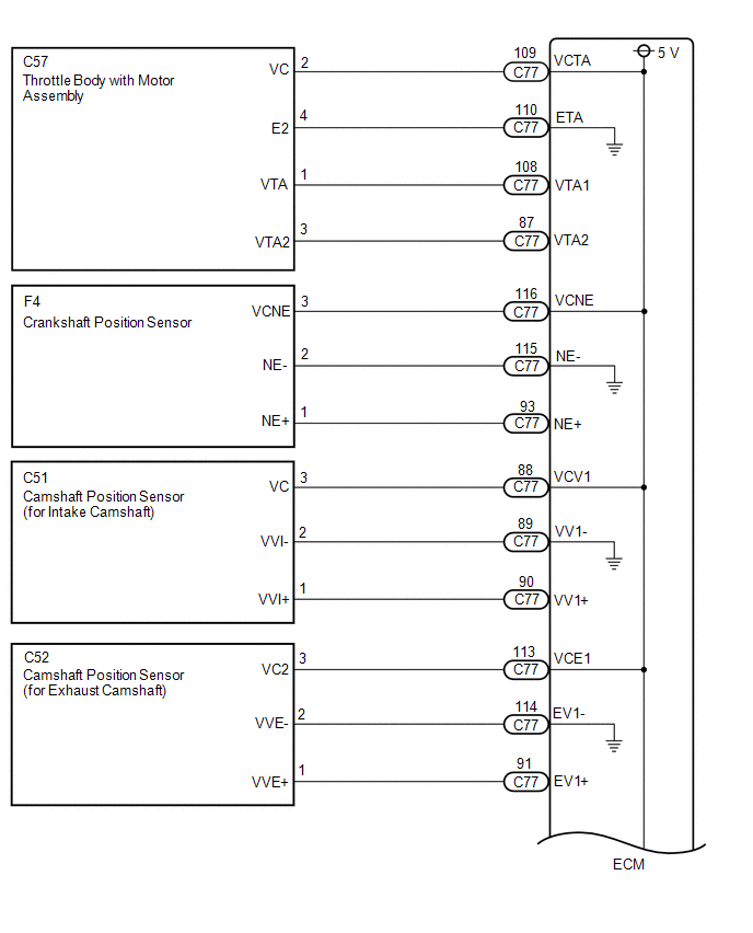
| C77-109 (VCTA) - Body ground | Always | 10 kΩ or higher |
| C77-116 (VCNE) - Body ground | Always | 10 kΩ or higher |
| C77-88 (VCV1) - Body ground | Always | 10 kΩ or higher |
| C77-113 (VCE1) - Body ground | Always | 10 kΩ or higher |
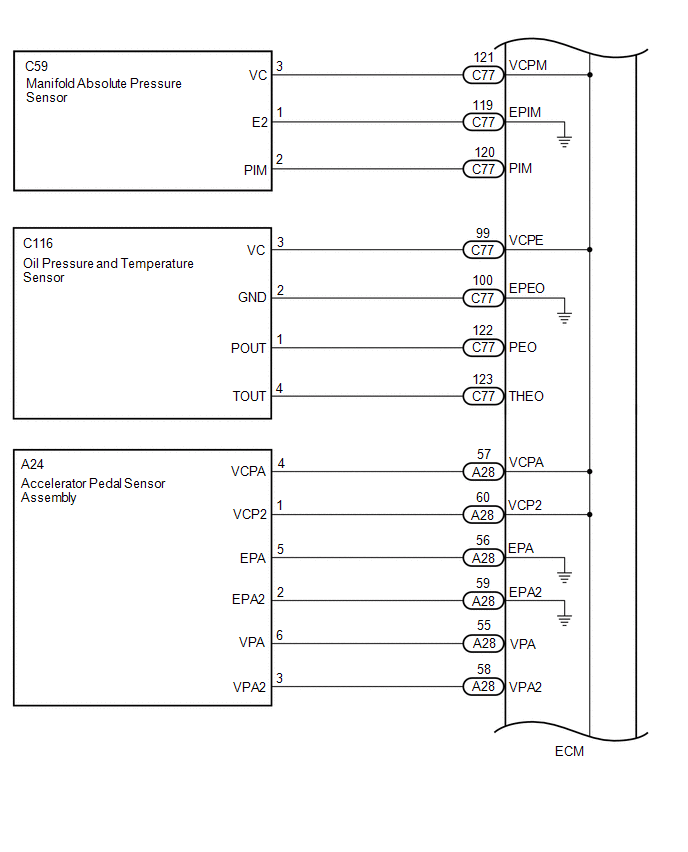
| C77-121 (VCPM) - Body ground | Always | 10 kΩ or higher |
| C77-99 (VCPE) - Body ground | Always | 10 kΩ or higher |
| A28-57 (VCPA) - Body ground | Always | 10 kΩ or higher |
| A28-60 (VCP2) - Body ground | Always | 10 kΩ or higher |
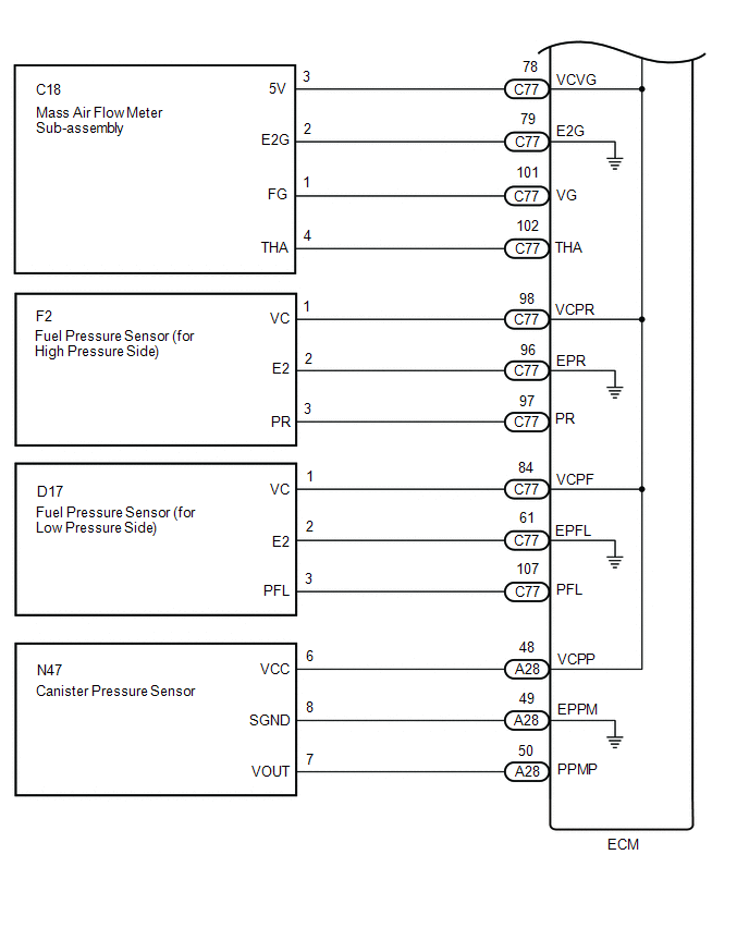
| C77-78 (VCVG) - Body ground | Always | 10 kΩ or higher |
| C77-98 (VCPR) - Body ground | Always | 10 kΩ or higher |
| C77-84 (VCPF) - Body ground | Always | 10 kΩ or higher |
| A28-48 (VCPP) - Body ground | Always | 10 kΩ or higher |
(n) Measure the resistance according to the value(s) in the table below.
HINT:
Remove the VVT, EFI-MAIN NO. 2 and A/F HTR relays connected between the checked terminals as the coil inside the relay influences the measurement value.
Standard Resistance:
| Tester Connection | Condition | Specified Condition |
|---|---|---|
| A28-9 (+B) - 1 (EFI NO. 1 fuse) | Always | Below 1 Ω |
| A28-35 (+B2) - 1 (EFI NO. 1 fuse) | Always | Below 1 Ω |
| A28-9 (+B) - Body ground | Always | 10 kΩ or higher |
| A28-35 (+B2) - Body ground | Always | 10 kΩ or higher |
| OK | | REPLACE ECM |
| NG | | REPAIR OR REPLACE HARNESS OR CONNECTOR |
READ NEXT:
 Starter Signal Circuit
DESCRIPTION While the engine is being cranked, current flows from terminal STAR of the certification ECU (smart key ECU assembly) to the park/neutral position switch assembly and to terminal STA of th
Brake Override System
DESCRIPTION When the vehicle is being driven, depressing the accelerator pedal sensor assembly and brake pedal will activate the brake override system to restrict engine output. The conditions for act
MIL Circuit
DESCRIPTION The Malfunction Indicator Lamp (MIL) is used to indicate vehicle malfunctions detected by the ECM. The MIL operation can be checked visually. When the engine switch is first turned on (IG)
SEE MORE:
Precaution
PRECAUTION PRECAUTION FOR DISCONNECTING CABLE FROM NEGATIVE AUXILIARY BATTERY TERMINAL NOTICE: When disconnecting the cable from the negative (-) auxiliary battery terminal, initialize the following systems after the cable is reconnected. System Name See Procedure Lane Control System (for H
Generator Position Sensor Circuit Voltage Below Threshold (P0A4B16,P0A4B1F)
DTC SUMMARY MALFUNCTION DESCRIPTION These DTCs indicate that the resolver output signal is abnormal. The cause of this malfunction may be one of the following: Area Main Malfunction Description Inverter low-voltage circuit The connectors are not connected properly Hybrid Vehicle Trans
