Lexus ES: Driver Side Power Window does not Operate with Power Window Master Switch
DESCRIPTION
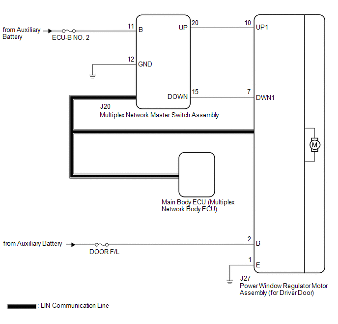
When the power switch is on (IG), the power window regulator motor assembly (for driver door) is operated by the multiplex network master switch assembly. The power window regulator motor assembly (for driver door) has motor, regulator and ECU functions.
WIRING DIAGRAM
CAUTION / NOTICE / HINT
NOTICE:
-
The power window control system uses the LIN communication system. Inspect the communication function by following How to Proceed with Troubleshooting. Troubleshoot the power window control system after confirming that the communication system is functioning properly.
Click here
.gif)
-
If the power window regulator motor assembly (for driver door) has been replaced with a new one, initialize the power window control system.
Click here
- Inspect the fuses for circuits related to this system before performing the following procedure.
-
Before replacing the main body ECU (multiplex network body ECU), refer to Registration.
Click here
PROCEDURE
| 1. | READ VALUE USING TECHSTREAM (MAIN BODY) |
(a) Connect the Techstream to the DLC3.
(b) Turn the power switch on (IG).
(c) Turn the Techstream on.
(d) Enter the following menus: Body Electrical / Main Body / Data List.
(e) Read the Data List according to the display on the Techstream.
Body Electrical > Main Body > Data List| Tester Display | Measurement Item | Range | Normal Condition | Diagnostic Note |
|---|---|---|---|---|
| Communication D-Door Motor | Connection status between power window regulator motor assembly (for driver door) and main body ECU (multiplex network body ECU) | STOP or OK | STOP: Communication stopped OK: Normal communication | - |
| Communication Master SW | Connection status between multiplex network master switch assembly and main body ECU (multiplex network body ECU) | STOP or OK | STOP: Communication stopped OK: Normal communication | - |
| Tester Display |
|---|
| Communication D-Door Motor |
| Communication Master SW |
OK:
OK is displayed for each Data List item above.
| NG | .gif) | GO TO LIN COMMUNICATION SYSTEM (Proceed to How to Proceed with Troubleshooting) |
|
.gif)
| 2. | READ VALUE USING TECHSTREAM (D-DOOR MOTOR) |
(a) Enter the following menus: Body Electrical / D-Door Motor / Data List.
(b) Read the Data List according to the display on the Techstream.
Body Electrical > D-Door Motor > Data List| Tester Display | Measurement Item | Range | Normal Condition | Diagnostic Note |
|---|---|---|---|---|
| D Door P/W Up SW | Driver door power window manual up switch signal | OFF or ON | OFF: Driver door power window manual up switch not being operated ON: Driver door power window manual up switch being operated | - |
| D Door P/W Down SW | Driver door power window manual down switch signal | OFF or ON | OFF: Driver door power window manual down switch not being operated ON: Driver door power window manual down switch being operated | - |
| Tester Display |
|---|
| D Door P/W Up SW |
| D Door P/W Down SW |
OK:
On the Techstream screen, ON or OFF is displayed accordingly.
| NG | | GO TO STEP 4 |
|
| 3. | PERFORM ACTIVE TEST USING TECHSTREAM (D-DOOR MOTOR) |
(a) Enter the following menus: Body Electrical / D-Door Motor / Active Test.
(b) Perform the Active Test according to the display on the Techstream.
CAUTION:
Be careful to avoid injuries as this test causes vehicle parts to move. During the Active Test, the jam protection function will not operate.
Body Electrical > D-Door Motor > Active Test| Tester Display | Measurement Item | Control Range | Diagnostic Note |
|---|---|---|---|
| Power Window | Power window | OFF / DOWN / UP | - |
| Tester Display |
|---|
| Power Window |
OK:
Driver door power window operates normally.
| OK | | REPLACE MAIN BODY ECU (MULTIPLEX NETWORK BODY ECU) |
| NG | | REPLACE POWER WINDOW REGULATOR MOTOR ASSEMBLY (for Driver Door) |
| 4. | CHECK HARNESS AND CONNECTOR (MULTIPLEX NETWORK MASTER SWITCH ASSEMBLY - POWER WINDOW REGULATOR MOTOR ASSEMBLY (for Driver Door)) |
(a) Disconnect the J20 multiplex network master switch assembly connector.
(b) Disconnect the J27 power window regulator motor assembly (for driver door) connector.
(c) Measure the resistance according to the value(s) in the table below.
Standard Resistance:
| Tester Connection | Condition | Specified Condition |
|---|---|---|
| J20-20 (UP) - J27-10 (UP1) | Always | Below 1 Ω |
| J20-20 (UP) or J27-10 (UP1) - Body ground | Always | 10 kΩ or higher |
| J20-15 (DOWN) - J27-7 (DWN1) | Always | Below 1 Ω |
| J20-15 (DOWN) or J27-7 (DWN1) - Body ground | Always | 10 kΩ or higher |
| NG | | REPAIR OR REPLACE HARNESS OR CONNECTOR |
|
| 5. | INSPECT POWER WINDOW REGULATOR MOTOR ASSEMBLY (for Driver Door) |
(a) Remove the power window regulator motor assembly (for driver door).
Click here
(b) Inspect the power window regulator motor assembly (for driver door).
Click here
| OK | | REPLACE MULTIPLEX NETWORK MASTER SWITCH ASSEMBLY |
| NG | | REPLACE POWER WINDOW REGULATOR MOTOR ASSEMBLY (for Driver Door) |
READ NEXT:
 Remote Up / Down Function does not Operate
DESCRIPTION When the power switch on (IG), the multiplex network master switch assembly sends remote up and down signals to each power window regulator motor assembly via LIN communication. WIRING DIA
Front Passenger Side Power Window does not Operate with Front Passenger Side Power Window Switch
DESCRIPTION When the power switch is on (IG), the power window regulator motor assembly (for front passenger door) is operated by the power window regulator switch assembly. The power window regulator
Rear Power Window LH does not Operate with Rear Power Window Switch LH
DESCRIPTION When the power switch is on (IG), the power window regulator motor assembly (for rear LH door) is operated by the rear power window regulator switch assembly (for LH door). The power windo
SEE MORE:
Customize Parameters
CUSTOMIZE PARAMETERS CUSTOMIZE ADAPTIVE VARIABLE SUSPENSION SYSTEM HINT: "Custom" mode can be selected by using the drive mode select switch (combination switch assembly). (a) Customizing with the multi-display (1) Turn the engine switch on (IG). (2) Enter the following menus: MENU / Setup / Vehicle
Lost Communication With ECM/PCM "A" (U0100,...,U1117)
DESCRIPTION These DTCs are stored if a CAN communication malfunction occurs between the main body ECU (multiplex network body ECU) and other ECUs. DTC No. Detection Item DTC Detection Condition Trouble Area DTC Output from U0100 Lost Communication With ECM/PCM "A" The main body EC
