Lexus ES: Drive Motor "A" Control Module Unexpected Operation (P0A1B94)
DTC SUMMARY
MALFUNCTION DESCRIPTION
The hybrid vehicle control ECU monitors the motor generator control ECU (MG ECU).
The cause of this malfunction may be the following:
- Motor generator control ECU (MG ECU) malfunction
DESCRIPTION
The hybrid vehicle control ECU monitors the motor generator control ECU (MG ECU) and stores this DTC when it detects a malfunction.
| DTC No. | Detection Item | DTC Detection Condition | Trouble Area | MIL | Warning Indicate |
|---|---|---|---|---|---|
| P0A1B94 | Drive Motor "A" Control Module Unexpected Operation | The motor generator control ECU (MG ECU) value received by the hybrid vehicle control ECU exceeds the threshold for a certain period of time. (1 trip detection logic) |
| Comes on | Master Warning Light: Comes on |
MONITOR DESCRIPTION
The hybrid vehicle control ECU monitors the motor generator control ECU (MG ECU). If the internal operation is malfunctioning, the hybrid vehicle control ECU illuminates the MIL and stores a DTC.
MONITOR STRATEGY
| Related DTCs | P0A1B (INF P0A1B94): Drive motor "A" control module |
| Required sensors/components | Inverter with converter assembly (MG ECU) |
| Frequency of operation | Continuous |
| Duration | TMC's intellectual property |
| MIL operation | 1 driving cycle |
| Sequence of operation | None |
TYPICAL ENABLING CONDITIONS
| The monitor will run whenever the following DTCs are not stored | TMC's intellectual property |
| Other conditions belong to TMC's intellectual property | - |
TYPICAL MALFUNCTION THRESHOLDS
| TMC's intellectual property | - |
COMPONENT OPERATING RANGE
| Hybrid vehicle control ECU | DTC P0A1B (INF P0A1B94) is not detected |
CONFIRMATION DRIVING PATTERN
HINT:
-
After repair has been completed, clear the DTC and then check that the vehicle has returned to normal by performing the following All Readiness check procedure.
Click here
.gif)
-
When clearing the permanent DTCs, refer to the "CLEAR PERMANENT DTC" procedure.
Click here
- Connect the Techstream to the DLC3.
- Turn the power switch on (IG) and turn the Techstream on.
- Clear the DTCs (even if no DTCs are stored, perform the clear DTC procedure).
- Turn the power switch off and wait for 2 minutes or more.
- Turn the power switch on (IG) and turn the Techstream on.
-
With power switch on (IG) and wait for 2 minutes or more. [*1]
HINT:
- If the vehicle has returned to normal, it can be driven after turning the power switch on (READY).
-
[*1] : Normal judgment procedure.
The normal judgment procedure is used to complete DTC judgment and also used when clearing permanent DTCs.
- Enter the following menus: Powertrain / Hybrid Control / Utility / All Readiness.
-
Check the DTC judgment result.
HINT:
- If the judgment result shows NORMAL, the system is normal.
- If the judgment result shows ABNORMAL, the system has a malfunction.
- If the judgment result shows INCOMPLETE or N/A, perform the normal judgment procedure again.
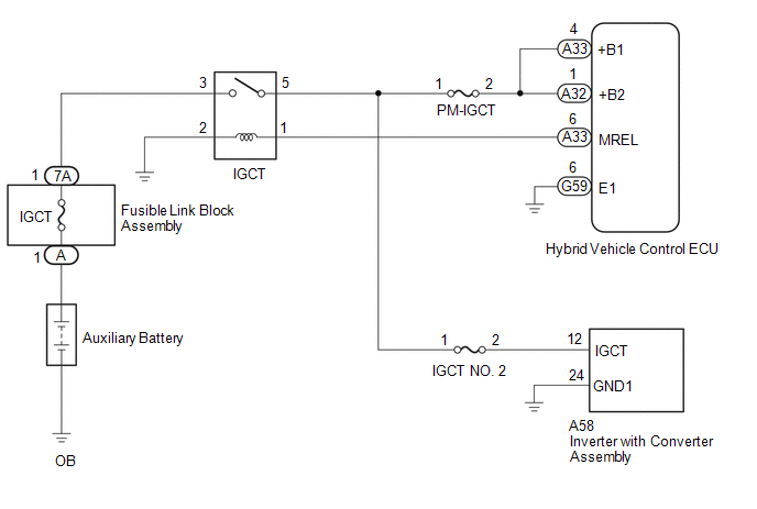
WIRING DIAGRAM
CAUTION / NOTICE / HINT
NOTICE:
After turning the power switch off, waiting time may be required before disconnecting the cable from the negative (-) auxiliary battery terminal. Therefore, make sure to read the disconnecting the cable from the negative (-) auxiliary battery terminal notices before proceeding with work.
Click here
PROCEDURE
| 1. | CHECK AUXILIARY BATTERY TERMINAL (CONTACT PROBLEM) |
(a) Check the connection of the negative (-) and positive (+) auxiliary battery terminals.
OK:
The terminals are connected securely and there is no contact problem.
HINT:
If performing a reproduction test, turn the power switch on (IG) and shake the wire harnesses vertically and horizontally before checking for DTCs.
| NG | .gif) | GO TO STEP 6 |
|
.gif)
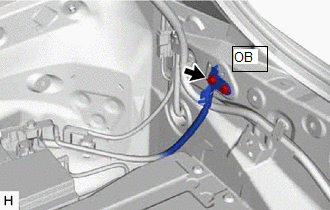
| 2. | CHECK GROUND WIRE CONNECTION CONDITION |
| (a) Check the installation condition of the ground wires OB. OK: The ground wires OB are securely installed. HINT: If performing a reproduction test, turn the power switch on (IG) and shake the wire harnesses vertically and horizontally before checking for DTCs. |
|
| NG | | GO TO STEP 7 |
|
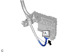
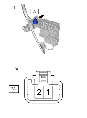
| 3. | CHECK FUSIBLE LINK (IGCT) |
(a) Disconnect the cable from the negative (-) auxiliary battery terminal.
(b) Disconnect the cable from the positive (+) auxiliary battery terminal.
(c) Check the fusible link block assembly (IGCT) for improper installation.
OK:
The fusible link block assembly is installed securely and there is no contact problem.
| (d) Disconnect the 7A fusible link block assembly connector. |
|
| (e) Measure the resistance according to the value(s) in the table below. Standard Resistance:
|
|
(f) Reconnect the 7A fusible link block assembly connector.
(g) Reconnect the cable from the positive (+) auxiliary battery terminal.
(h) Reconnect the cable from the negative (-) auxiliary battery terminal.
| NG | | GO TO STEP 8 |
|
| 4. | CHECK RELAY (IGCT) |
(a) Check the IGCT relay for improper installation.
OK:
The relay is installed securely.
HINT:
If performing a reproduction test, turn the power switch on (IG) and gently vibrate the IGCT relay with a finger before checking for DTCs.
| (b) Remove the IGCT relay from the No. 3 relay block. |
|
| (c) Measure the resistance according to the value(s) in the table below. Standard Resistance:
|
|
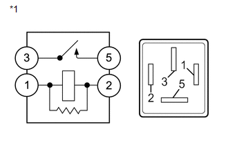
(d) Install the IGCT relay.
| NG | | GO TO STEP 9 |
|
| 5. | CHECK DTC OUTPUT (HYBRID CONTROL) |
(a) Connect the Techstream to the DLC3.
(b) Turn the power switch on (IG).
(c) Enter the following menus: Powertrain / Hybrid Control / Trouble Codes.
(d) Check for DTCs.
HINT:
Check the DTCs that were output when the vehicle was brought to the workshop.
Powertrain > Hybrid Control > Trouble Codes| Result | Proceed to |
|---|---|
| P0A1B94 only is output | A |
| DTCs except P0A1B94 are output | B |
(e) Turn the power switch off.
| A | | REFER TO REPLACE INVERTER WITH CONVERTER ASSEMBLY PARTS |
| B | | GO TO DTC CHART (HYBRID CONTROL SYSTEM) |
| 6. | CONNECT SECURELY |
| NEXT | | GO TO STEP 10 |
| 7. | CONNECT SECURELY |
| NEXT | | GO TO STEP 10 |
| 8. | REPAIR OR REPLACE MALFUNCTIONING PARTS |
| NEXT | | GO TO STEP 10 |
| 9. | REPAIR OR REPLACE MALFUNCTIONING PARTS |
|
| 10. | CLEAR DTC |
Click here
|
| 11. | SIMULATION TEST |
(a) Turn the power switch on (IG) and wait for 2 minutes or more.
(b) Turn the power switch off.
|
| 12. | CHECK DTC OUTPUT (HYBRID CONTROL) |
(a) Connect the Techstream to the DLC3.
(b) Turn the power switch on (IG).
(c) Enter the following menus: Powertrain / Hybrid Control / Trouble Codes.
Powertrain > Hybrid Control > Trouble Codes(d) Check for DTCs.
| Result | Proceed to |
|---|---|
| No DTCs are output | A |
| P0A1B94 only is output | B |
| DTCs except P0A1B94 are output | C |
(e) Turn the power switch off.
| A | | END |
| B | | REFER TO REPLACE INVERTER WITH CONVERTER ASSEMBLY PARTS |
| C | | GO TO DTC CHART (HYBRID CONTROL SYSTEM) |
READ NEXT:
 Hybrid/EV Battery Energy Control Module Unexpected Operation (P0A1F94)
DTC SUMMARY MALFUNCTION DESCRIPTION The hybrid vehicle control ECU (main CPU) monitors the battery ECU assembly. The cause of this malfunction may be the following: Battery ECU assembly internal malf
Drive Motor "A" Temperature Sensor Circuit Short to Ground (P0A2A11,P0A2A15)
DTC SUMMARY MALFUNCTION DESCRIPTION These DTCs are stored when the motor temperature sensor output is abnormal. The cause of this malfunction may be one of the following: Hybrid vehicle control ECU m
Drive Motor "A" Temperature Sensor Voltage Out of Range (P0A2A1C,P0A2A1F)
DTC SUMMARY MALFUNCTION DESCRIPTION These DTCs are stored when the motor temperature sensor output is abnormal. The cause of this malfunction may be one of the following: Motor temperature sensor mal
SEE MORE:
Data List / Active Test
DATA LIST / ACTIVE TEST DATA LIST NOTICE: In the table below, the values listed under "Normal Condition" are reference values. Do not depend solely on these reference values when deciding whether a part is faulty or not. (a) Connect the Techstream to the DLC3. (b) Turn the power switch on (IG). (c)
Malfunction in Yaw Rate Sensor (C1436)
DESCRIPTION The airbag ECU assembly has a built-in yaw rate and acceleration sensor and detects the vehicle condition using 2 circuits (GL1, GL2). When the skid control ECU (brake booster with master cylinder assembly) detects improper installation of the yaw rate and acceleration sensor (airbag ECU
