Lexus ES: Drive Motor "A" Temperature Sensor Circuit Short to Ground (P0A2A11,P0A2A15)
DTC SUMMARY
MALFUNCTION DESCRIPTION
These DTCs are stored when the motor temperature sensor output is abnormal. The cause of this malfunction may be one of the following:
- Hybrid vehicle control ECU internal malfunction
- Internal motor temperature sensor malfunction
- Open or short in motor temperature sensor
- The connectors are not connected properly
- Foreign matter or water on the connector terminals
- Open or short in wire harness
HINT:
If any of these DTCs are stored, the motor temperature sensor is malfunctioning and the self-protection function may not operate. Therefore under certain high load driving condition, the temperature of the motor (MG2) becomes high. If the self-protection function does not operate, the motor (MG2) may malfunction and cause the vehicle to enter fail-safe mode.
DESCRIPTION
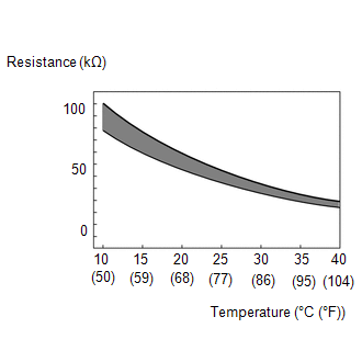
The resistance of the thermistor built into the motor temperature sensor changes in accordance with changes in the motor (MG2) temperature. The lower the motor (MG2) temperature, the higher the thermistor resistance. Conversely, the higher the motor (MG2) temperature, the lower the resistance.
HINT:
The term "drive motor A" indicates the motor (MG2).
| DTC No. | Detection Item | DTC Detection Condition | Trouble Area | MIL | Warning Indicate |
|---|---|---|---|---|---|
| P0A2A11 | Drive Motor "A" Temperature Sensor Circuit Short to Ground | Short to ground in the motor temperature sensor circuit (1 trip detection logic) |
| Comes on | Master Warning Light: Comes on |
| P0A2A15 | Drive Motor "A" Temperature Sensor Circuit Short to Auxiliary Battery or Open | Open or short to +B in the motor temperature sensor circuit (1 trip detection logic) |
| Comes on | Master Warning Light: Comes on |
| DTC No. | Data List |
|---|---|
| P0A2A11 | Motor Temperature |
| P0A2A15 |
HINT:
After confirming that DTC P0A2A11 or P0A2A15 is output, use the Techstream to check "Motor Temperature" in the Data List.
| Displayed Temperature | Malfunction |
|---|---|
| -40°C (-40°F) | Open circuit or short to +B |
| 215°C (419°F) | Short to ground |
MONITOR DESCRIPTION
If the hybrid vehicle control ECU detects a malfunction of the motor temperature sensor, it will illuminate the MIL and store a DTC.
MONITOR STRATEGY
| Related DTCs | P0A2C (INF P0A2A11): Drive Motor "A" Temperature Sensor Circuit Low P0A2D (INF P0A2A15): Drive Motor "A" Temperature Sensor Circuit High |
| Required sensors/components | Motor temperature sensor |
| Frequency of operation | Continuous |
| Duration | TMC's intellectual property |
| MIL operation | 1 driving cycle |
| Sequence of operation | None |
TYPICAL ENABLING CONDITIONS
| The monitor will run whenever the following DTCs are not stored | TMC's intellectual property |
| Other conditions belong to TMC's intellectual property | - |
TYPICAL MALFUNCTION THRESHOLDS
| TMC's intellectual property | - |
COMPONENT OPERATING RANGE
| Hybrid vehicle control ECU | DTC P0A2C (INF P0A2A11) is not detected DTC P0A2D (INF P0A2A15) is not detected |
CONFIRMATION DRIVING PATTERN
HINT:
-
After repair has been completed, clear the DTC and then check that the vehicle has returned to normal by performing the following All Readiness check procedure.
Click here
.gif)
-
When clearing the permanent DTCs, refer to the "CLEAR PERMANENT DTC" procedure.
Click here
- Connect the Techstream to the DLC3.
- Turn the power switch on (IG) and turn the Techstream on.
- Clear the DTCs (even if no DTCs are stored, perform the clear DTC procedure).
- Turn the power switch off and wait for 2 minutes or more.
- Turn the power switch on (IG) and turn the Techstream on.
-
With power switch on (IG) and wait for 5 seconds or more.[*1]
HINT:
[*1] : Normal judgment procedure.
The normal judgment procedure is used to complete DTC judgment and also used when clearing permanent DTCs.
- Enter the following menus: Powertrain / Hybrid Control / Utility / All Readiness.
-
Check the DTC judgment result.
HINT:
- If the judgment result shows NORMAL, the system is normal.
- If the judgment result shows ABNORMAL, the system has a malfunction.
- If the judgment result shows INCOMPLETE or N/A, perform the normal judgment procedure again.
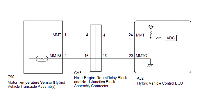
WIRING DIAGRAM
PROCEDURE
| 1. | CHECK CONNECTOR CONNECTION CONDITION (HYBRID VEHICLE CONTROL ECU CONNECTOR) |
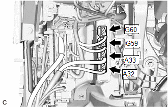
| (a) Check the connection condition of the hybrid vehicle control ECU connectors and the contact pressure of each terminal. Check the terminals for deformation, and check the connector for water ingress and foreign matter. Click here OK: - The connector is connected securely. - The terminals are not deformed and are connected securely. - No water or foreign matter in the connector.
|
|
| B | .gif) | CONNECT SECURELY |
| C | | REPAIR OR REPLACE HARNESS OR CONNECTOR |
|
.gif)
| 2. | CHECK CONNECTOR CONNECTION CONDITION (INTERMEDIATE CONNECTOR) |
(a) Check that the intermediate connector which connects the motor temperature sensor to the hybrid vehicle control ECU is securely connected with no deformation, and that there is no contamination by water or foreign matter.
Click here
HINT:
For vehicles in which the intermediate connector is inside the relay block, check for signs of water intrusion inside the relay block.
OK:
- The connector is connected securely.
- The terminals are not deformed and are connected securely.
- No water or foreign matter in the connectors.
| Result | Proceed to |
|---|---|
| OK | A |
| NG (The connector is not connected securely.) | B |
| NG (The terminals are not making secure contact or are deformed, or water or foreign matter exists in the connector.) | C |
| B | | CONNECT SECURELY |
| C | | REPAIR OR REPLACE HARNESS OR CONNECTOR |
|
| 3. | CHECK CONNECTOR CONNECTION CONDITION (MOTOR TEMPERATURE SENSOR CONNECTOR) |
| (a) Check the connection condition of the motor temperature sensor connector and the contact pressure of each terminal. Check the terminals for deformation, and check the connector for water ingress and foreign matter. Click here OK: - The connector is connected securely. - The terminals are not deformed and are connected securely. - No water or foreign matter in the connector. |
|
| Result | Proceed to |
|---|---|
| OK | A |
| NG (The connector is not connected securely.) | B |
| NG (The terminals are not making secure contact or are deformed, or water or foreign matter exists in the connector.) | C |
| B | | CONNECT SECURELY |
| C | | REPAIR OR REPLACE HARNESS OR CONNECTOR |
|
| 4. | READ VALUE USING TECHSTREAM (MOTOR TEMPERATURE) |
(a) Connect the Techstream to the DLC3.
(b) Turn the power switch on (IG).
(c) Enter the following menus: Powertrain / Hybrid Control / Data List / Motor Temperature.
Powertrain > Hybrid Control > Data List| Tester Display |
|---|
| Motor Temperature |
(d) Read the Data List.
| Result | Proceed to |
|---|---|
| -40°C (-40°F) | A |
| 215°C (419°F) | B |
| Same as actual temperature | C |
(e) Turn the power switch off.
| B | | GO TO STEP 7 |
| C | | REPAIR OR REPLACE HARNESS OR CONNECTOR |
|
| 5. | INSPECT HYBRID VEHICLE TRANSAXLE ASSEMBLY (MOTOR TEMPERATURE SENSOR) |
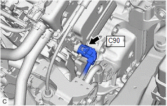
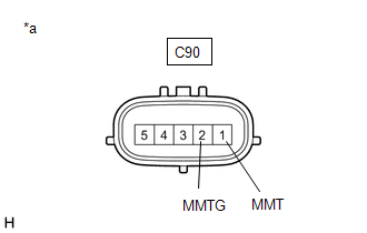
| (a) Disconnect the C90 motor temperature sensor connector. |
|
| (b) Measure the resistance according to the value(s) in the table below. Standard Resistance:
HINT: Terminal No. 3 on the component side connector is empty. |
|
(c) Reconnect the C90 motor temperature sensor connector.
| NG | | REPLACE HYBRID VEHICLE TRANSAXLE ASSEMBLY |
|
| 6. | CHECK HYBRID VEHICLE CONTROL ECU |
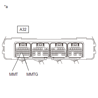
| (a) Connect terminals 24 (MMT) and 23 (MMTG) of the A32 hybrid vehicle control ECU connector. |
|
(b) Connect the Techstream to the DLC3.
(c) Turn the power switch on (IG).
(d) Enter the following menus: Powertrain / Hybrid Control / Data List / Motor Temperature.
Powertrain > Hybrid Control > Data List| Tester Display |
|---|
| Motor Temperature |
(e) Read the Data List.
OK:
| Techstream Display | Condition | Specified Condition |
|---|---|---|
| Motor Temperature | Terminals A32-24 (MMT) and A32-23 (MMTG) connected Power switch on (IG) | 215°C (419°F) |
(f) Turn the power switch off.
| OK | | REPAIR OR REPLACE HARNESS OR CONNECTOR (MOTOR TEMPERATURE SENSOR - HYBRID VEHICLE CONTROL ECU) |
| NG | | REPLACE HYBRID VEHICLE CONTROL ECU |
| 7. | INSPECT HYBRID VEHICLE TRANSAXLE ASSEMBLY (MOTOR TEMPERATURE SENSOR) |
| (a) Disconnect the C90 motor temperature sensor connector. |
|
| (b) Measure the resistance according to the value(s) in the table below. Standard Resistance:
HINT: Terminal No. 3 on the component side connector is empty. |
|
(c) Reconnect the C90 motor temperature sensor connector.
| NG | | REPLACE HYBRID VEHICLE TRANSAXLE ASSEMBLY |
|
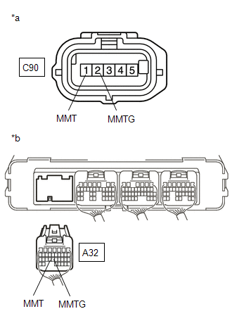
| 8. | CHECK HARNESS AND CONNECTOR (MOTOR TEMPERATURE SENSOR - HYBRID VEHICLE CONTROL ECU) |
(a) Disconnect the C90 motor temperature sensor connector.
(b) Disconnect the A32 hybrid vehicle control ECU connector.
| (c) Measure the resistance according to the value(s) in the table below. Standard Resistance (Check for Open):
Standard Resistance (Check for Short):
|
|
(d) Reconnect the A32 hybrid vehicle control ECU connector.
(e) Reconnect the C90 motor temperature sensor connector.
| OK | | REPLACE HYBRID VEHICLE CONTROL ECU |
| NG | | REPAIR OR REPLACE HARNESS OR CONNECTOR |
READ NEXT:
 Drive Motor "A" Temperature Sensor Voltage Out of Range (P0A2A1C,P0A2A1F)
DTC SUMMARY MALFUNCTION DESCRIPTION These DTCs are stored when the motor temperature sensor output is abnormal. The cause of this malfunction may be one of the following: Motor temperature sensor mal
Generator Temperature Sensor Voltage Out of Range (P0A361C,P0A361F)
DTC SUMMARY MALFUNCTION DESCRIPTION These DTCs are stored when the generator temperature sensor output is abnormal. The cause of this malfunction may be one of the following: Generator temperature se
Generator Temperature Sensor Circuit Short to Ground (P0A3611,P0A3615)
DTC SUMMARY MALFUNCTION DESCRIPTION These DTCs are stored when the generator temperature sensor output is abnormal. The cause of this malfunction may be one of the following: Hybrid vehicle control E
SEE MORE:
Installation
INSTALLATION CAUTION / NOTICE / HINT NOTICE: This procedure includes the installation of small-head bolts. Refer to Small-Head Bolts of Basic Repair Hint to identify the small-head bolts. Click here PROCEDURE 1. INSTALL OIL PRESSURE CONTROL VALVE ASSEMBLY (a) Apply a small amount of engine oil
Precaution
PRECAUTION PRECAUTION FOR DISCONNECTING CABLE FROM NEGATIVE BATTERY TERMINAL NOTICE: When disconnecting the cable from the negative (-) battery terminal, initialize the following systems after the cable is reconnected. System Name See Procedure Lane Control System (for Gasoline Model)
