Lexus ES: Drive Mode Select Switch Circuit
DESCRIPTION
The characteristics of the electronic throttle and EPS operation change according to operation of the drive mode select switch (combination switch assembly).
WIRING DIAGRAM
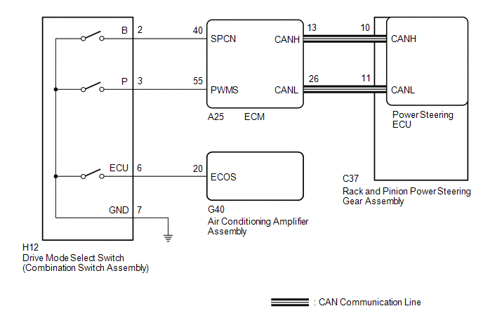
PROCEDURE
| 1. | CHECK THE PROBLEM SYMPTOMS |
(a) Check each symptom by checking the suspected areas in the table below.
| Result | Proceed to |
|---|---|
| SPORT mode or NORMAL mode is abnormal. | A |
| ECO mode is abnormal. | B |
| B | .gif) | GO TO AIR CONDITIONING SYSTEM |
|
.gif)
| 2. | CHECK CAN COMMUNICATION SYSTEM |
(a) Check for DTCs.
Click here .gif)
| Result | Proceed to |
|---|---|
| CAN communication system DTCs are not output. | A |
| CAN communication system DTCs are output. | B |
| B | | GO TO CAN COMMUNICATION SYSTEM |
|
| 3. | CHECK HARNESS AND CONNECTOR (DRIVE MODE SELECT SWITCH (COMBINATION SWITCH ASSEMBLY) - BODY GROUND) |
(a) Turn the engine switch off.
| (b) Disconnect the H12 drive mode select switch (combination switch assembly) connector. |
|
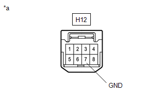
(c) Measure the resistance according to the value(s) in the table below.
Standard Resistance:
| Tester Connection | Condition | Specified Condition |
|---|---|---|
| H12-7 (GND) - Body ground | Always | Below 1 Ω |
| NG | | REPAIR OR REPLACE HARNESS OR CONNECTOR |
|
| 4. | INSPECT DRIVE MODE SELECT SWITCH (COMBINATION SWITCH ASSEMBLY) |
(a) Inspect drive mode select switch (combination switch assembly).
Click here
OK:
Drive mode select switch (Combination switch assembly) is normal.
| Result | Proceed to |
|---|---|
| CAN communication system DTCs are not output. | A |
| CAN communication system DTCs are output. | B |
| B | | REPLACE COMBINATION SWITCH ASSEMBLY |
|
| 5. | CHECK HARNESS AND CONNECTOR (DRIVE MODE SELECT SWITCH (COMBINATION SWITCH ASSEMBLY) - ECM) |
(a) Connect the H12 drive mode select switch (combination switch assembly) connector.
| (b) Disconnect the A25 ECM connectors. |
|
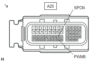
(c) Measure the resistance according to the value(s) in the table below.
Standard Resistance:
w/ Adaptive Variable Suspension System| Tester Connection | Condition | Specified Condition |
|---|---|---|
| A25-55 (PWMS) - Body ground | SPORT S/S+ mode switch being turned and held | Below 1 Ω |
| A25-55 (PWMS) - Body ground | SPORT S/S+ mode switch not turned | 10 kΩ or higher |
| A25-40 (SPCN) - Body ground | NORMAL/CUSTOM mode switch being pushed and held | Below 1 Ω |
| A25-40 (SPCN) - Body ground | NORMAL/CUSTOM mode switch not pushed | 10 kΩ or higher |
| Tester Connection | Condition | Specified Condition |
|---|---|---|
| A25-55 (PWMS) - Body ground | SPORT mode switch being turned and held | Below 1 Ω |
| A25-55 (PWMS) - Body ground | SPORT mode switch not turned | 10 kΩ or higher |
| A25-40 (SPCN) - Body ground | NORMAL mode switch being pushed and held | Below 1 Ω |
| A25-40 (SPCN) - Body ground | NORMAL mode switch not pushed | 10 kΩ or higher |
| OK | | REPLACE ECM |
| NG | | REPAIR OR REPLACE HARNESS OR CONNECTOR |
READ NEXT:
 Drive Mode Select Switch Circuit
DESCRIPTION The characteristics of the electronic throttle and EPS operation change according to operation of the drive mode select switch (combination switch assembly). WIRING DIAGRAM PROCEDURE 1
Check Assist Limit Record
CAUTION / NOTICE / HINT HINT: Perform this troubleshooting procedure when no DTCs are output, including DTCs related to CAN communication system malfunctions. PROCEDURE 1. READ VALUE USING GTS (
SEE MORE:
Pressure Control Solenoid "L" Circuit Short to Battery (P08BA12)
DESCRIPTION Changing gears is performed by the ECM turning the solenoid (SL1, SL2, SL3, SL4, SL5 and SL6) valves on and off. If an open or short occurs in any of the solenoid valve circuits, the ECM controls the remaining normal solenoid valves to allow the vehicle to be driven. If all of the soleno
Lost Communication with Cruise Control Front Distance Range Sensor Signal Sensor or Center Missing Message (U023587)
DESCRIPTION The forward recognition camera and millimeter wave radar sensor assembly communicate via CAN communication. If there is an error in the communication with the millimeter wave radar sensor assembly, the forward recognition camera stores DTC U023587. DTC No. Detection Item DTC Detec
