Lexus ES: Disassembly
DISASSEMBLY
CAUTION / NOTICE / HINT
The necessary procedures (adjustment, calibration, initialization or registration) that must be performed after parts are removed and installed, or replaced during engine unit removal/installation are shown below.
Necessary Procedure After Parts Removed/Installed/Replaced| Replaced Part or Performed Procedure | Necessary Procedure | Effect/Inoperative Function when Necessary Procedure not Performed | Link |
|---|---|---|---|
| Battery terminal is disconnected/reconnected | Perform steering sensor zero point calibration | Lane Control System | |
| Pre-collision System | |||
| Parking Support Brake System*1 | |||
| Lighting System | |||
| Memorize steering angle neutral point | Parking Assist Monitor System | | |
| Panoramic View Monitor System | | ||
| Initialize power trunk lid system | Power Trunk Lid System | | |
| Replacement of ECM | Vehicle Identification Number (VIN) registration | MIL comes on | |
| ECU communication ID registration (Immobiliser system) | Engine start function | | |
| Inspection after repair |
| |
| Replacement of automatic transaxle assembly |
|
| for Initialization: for Registration: |
| Replacement of ECM (If transaxle compensation code read from ECM) |
| ||
| Replacement of ECM (If transaxle compensation code not read from ECM) |
| ||
| Replacement of ECM | Code registration (Smart access system with push-button start (for Start Function, Gasoline Model) |
| |
| Replacement of automatic transaxle fluid | ATF thermal degradation estimate reset | The value of the Data List item "ATF Thermal Degradation Estimate" is not estimated correctly | |
| Suspension, tires, etc. (The vehicle height changes because of suspension or tire replacement) | Rear television camera assembly optical axis adjustment (Back camera position setting) | Parking assist monitor system | for Initialization: for Calibration: |
| Perform headlight ECU sub-assembly LH initialization | Lighting system | | |
| Front wheel alignment adjustment |
|
| |
| Front television camera view adjustment | Panoramic View Monitor System | for Initialization for Calibration |
| Replacement of front bumper assembly |
|
| |
-
*1: When performing learning using the Techstream.
Click here
.gif)
- *2: Not necessary when ECM replaced with new one
NOTICE:
- After the engine switch is turned off, the radio receiver assembly records various types of memory and settings. As a result, after turning the engine switch off, make sure to wait at least 85 seconds before disconnecting the cable from the negative (-) battery terminal. (for Audio and Visual System)
- After the engine switch is turned off, the radio receiver assembly records various types of memory and settings. As a result, after turning the engine switch off, make sure to wait at least 85 seconds before disconnecting the cable from the negative (-) battery terminal. (for Navigation System)
PROCEDURE
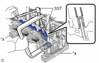
1. REMOVE INTAKE VALVE
| (a) Using SST and wooden blocks, compress the inner compression spring and remove the 6 valve spring retainer locks from the valve spring retainer. SST: 09202-70020 09202-01010 09202-01020 SST: 09202-00021 HINT: Arrange the removed parts in such a way that they can be reinstalled to their original locations. |
|
(b) Remove the 6 valve spring retainers, 6 inner compression springs and 6 intake valves from the cylinder head LH.
HINT:
Arrange the removed parts in such a way that they can be reinstalled to their original locations.
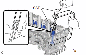
2. REMOVE EXHAUST VALVE
| (a) Using SST and wooden blocks, compress the inner compression spring and remove the 6 valve spring retainer locks from the valve spring retainer. SST: 09202-70020 09202-01010 09202-01020 SST: 09202-00021 HINT: Arrange the removed parts in such a way that they can be reinstalled to their original locations. |
|
(b) Remove the 6 valve spring retainers, 6 inner compression springs and 6 exhaust valves from the cylinder head LH.
HINT:
Arrange the removed parts in such a way that they can be reinstalled to their original locations.
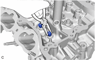
3. REMOVE INTAKE VALVE STEM OIL SEAL
| (a) Using needle-nose pliers, remove the 6 intake valve stem oil seals from the intake valve guide bush. |
|
4. REMOVE EXHAUST VALVE STEM OIL SEAL
HINT:
Use the same procedure as for the intake side.
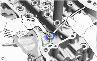
5. REMOVE VALVE SPRING SEAT
| (a) Using compressed air and a Magnet Hand, remove the 12 valve spring seats by blowing air onto them from the cylinder head LH. HINT: Arrange the removed parts in such a way that they can be reinstalled to their original locations. |
|
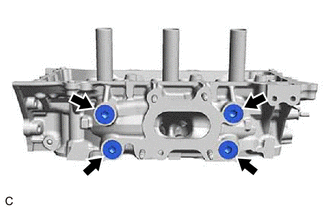
6. REMOVE NO. 1 STRAIGHT SCREW PLUG
NOTICE:
If coolant leaks from a No. 1 straight screw plug or a plug is corroded, replace it.
| (a) Using a 10 mm hexagon socket wrench, remove the 2 No. 1 straight screw plugs and 2 water hole gaskets from the cylinder head LH. |
|
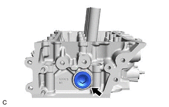
7. REMOVE NO. 2 STRAIGHT SCREW PLUG
NOTICE:
If coolant leaks from a No. 2 straight screw plug or a plug is corroded, replace it.
| (a) Using a 14 mm hexagon wrench, remove the No. 2 straight screw plug and cylinder head screw plug gasket from the cylinder head LH. |
|
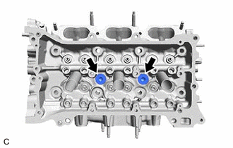
8. REMOVE NO. 3 STRAIGHT SCREW PLUG
NOTICE:
If coolant leaks from a No. 3 straight screw plug or a plug is corroded, replace it.
| (a) Using a 10 mm hexagon socket wrench, remove the 4 No. 3 straight screw plugs and 4 cylinder head screw plug gaskets from the cylinder head LH. |
|
READ NEXT:
 Inspection
INSPECTION CAUTION / NOTICE / HINT HINT:
Use the same procedure for bank 1 and bank 2.
The following procedure is for bank 2.
PROCEDURE 1. INSPECT CYLINDER HEAD LH (a) Using a precision straig
Replacement
REPLACEMENT CAUTION / NOTICE / HINT HINT:
Use the same procedure for bank 1 and bank 2.
The following procedure is for bank 2.
PROCEDURE 1. REPLACE INTAKE VALVE GUIDE BUSH (a) Heat the cylinde
Reassembly
REASSEMBLY CAUTION / NOTICE / HINT HINT:
Use the same procedure for bank 1 and bank 2.
The following procedure is for bank 2.
PROCEDURE 1. INSTALL SPARK PLUG TUBE HINT: When using a new cylind
SEE MORE:
Removal
REMOVAL PROCEDURE 1. SECURE VEHICLE (a) Fully apply the parking brake and chock a wheel. CAUTION:
Make sure to apply the parking brake and chock a wheel before performing this procedure.
If the vehicle is not secure and the shift lever is moved to N, the vehicle may suddenly move, possibly resu
Driver Side Camera Video Sync Signal Malfunction (C1686)
DESCRIPTION This DTC is stored if the parking assist ECU judges as a result of its self check that a synchronization problem is occurring in the image signal sent from the driver side television camera assembly to the parking assist ECU. DTC No. Detection Item DTC Detection Condition Troubl
