Lexus ES: Disassembly
DISASSEMBLY
CAUTION / NOTICE / HINT
The necessary procedures (adjustment, calibration, initialization or registration) that must be performed after parts are removed and installed, or replaced during engine unit removal/installation are shown below.
Necessary Procedure After Parts Removed/Installed/Replaced| Replaced Part or Performed Procedure | Necessary Procedure | Effect/Inoperative Function when Necessary Procedure not Performed | Link |
|---|---|---|---|
| Battery terminal is disconnected/reconnected | Perform steering sensor zero point calibration | Lane Control System | |
| Pre-collision System | |||
| Parking Support Brake System*1 | |||
| Lighting System | |||
| Memorize steering angle neutral point | Parking Assist Monitor System | | |
| Panoramic View Monitor System | | ||
| Initialize power trunk lid system | Power Trunk Lid System | | |
| Replacement of ECM | Vehicle Identification Number (VIN) registration | MIL comes on | |
| ECU communication ID registration (Immobiliser system) | Engine start function | | |
| Inspection after repair |
| |
| Replacement of automatic transaxle assembly |
|
| for Initialization: for Registration: |
| Replacement of ECM (If transaxle compensation code read from ECM) |
| ||
| Replacement of ECM (If transaxle compensation code not read from ECM) |
| ||
| Replacement of ECM | Code registration (Smart access system with push-button start (for Start Function, Gasoline Model) |
| |
| Replacement of automatic transaxle fluid | ATF thermal degradation estimate reset | The value of the Data List item "ATF Thermal Degradation Estimate" is not estimated correctly | |
| Suspension, tires, etc. (The vehicle height changes because of suspension or tire replacement) | Rear television camera assembly optical axis adjustment (Back camera position setting) | Parking assist monitor system | for Initialization: for Calibration: |
| Perform headlight ECU sub-assembly LH initialization | Lighting system | | |
| Front wheel alignment adjustment |
|
| |
| Front television camera view adjustment | Panoramic View Monitor System | for Initialization for Calibration |
| Replacement of front bumper assembly |
|
| |
-
*1: When performing learning using the Techstream.
Click here
.gif)
- *2: Not necessary when ECM replaced with new one
NOTICE:
- After the engine switch is turned off, the radio receiver assembly records various types of memory and settings. As a result, after turning the engine switch off, make sure to wait at least 85 seconds before disconnecting the cable from the negative (-) battery terminal. (for Audio and Visual System)
- After the engine switch is turned off, the radio receiver assembly records various types of memory and settings. As a result, after turning the engine switch off, make sure to wait at least 85 seconds before disconnecting the cable from the negative (-) battery terminal. (for Navigation System)
PROCEDURE
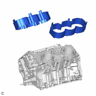
1. REMOVE CYLINDER BLOCK WATER JACKET SPACER
| (a) Remove the cylinder block water jacket spacer and cylinder block water jacket spacer LH from the cylinder block sub-assembly. |
|
2. REMOVE PISTON SUB-ASSEMBLY WITH CONNECTING ROD
(a) Check that the matchmarks on the connecting rod sub-assembly and connecting rod cap are aligned.
HINT:
The matchmarks on the connecting rod sub-assembly and connecting rod cap are guides for correct reassembly.
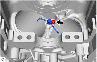
(b) Remove the 2 connecting rod bolts.
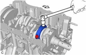
.png) | Front of Engine |
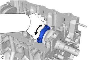
| (c) Using the 2 removed connecting rod bolts, remove the connecting rod cap and lower connecting rod bearing by wiggling the connecting rod cap right and left. HINT: Keep the lower connecting rod bearing installed to the connecting rod cap. |
|
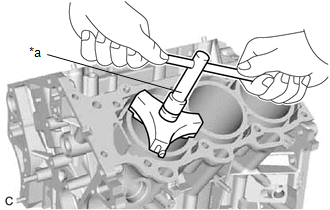
| (d) Using a ridge reamer, remove all of the carbon from the top of the cylinder. |
|
(e) Push the piston, connecting rod sub-assembly and upper connecting rod bearing through the top of the cylinder block sub-assembly.
HINT:
- Keep the connecting rod bearing, connecting rod sub-assembly and connecting rod cap together.
- Arrange the removed parts in such a way that they can be reinstalled to their original locations.
3. REMOVE CONNECTING ROD BEARING
(a) Remove the connecting rod bearings from the connecting rod sub-assembly and connecting rod cap.
HINT:
Arrange the removed parts in such a way that they can be reinstalled to their original locations.
4. REMOVE PISTON RING SET
| (a) Using a piston ring expander, remove the No. 1 compression ring and No. 2 compression ring. |
|
(b) Remove the oil ring expander and 2 side rails by hand.
HINT:
Arrange the removed parts in such a way that they can be reinstalled to their original locations.
5. REMOVE PISTON
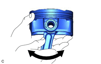
| (a) Check the fitting condition between the piston and piston pin. (1) Try to move the piston back and forth on the piston pin. HINT: If abnormal movement is felt, replace the piston and piston pin as a set. |
|
(b) Remove the connecting rod sub-assembly from the piston.
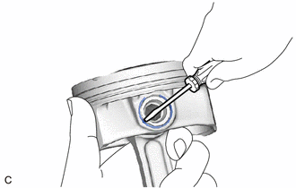
(1) Using a screwdriver, pry out the piston pin hole snap ring (front side).
NOTICE:
- Do not remove the piston pin hole snap ring (rear side) unless it has to be replaced.
- Be careful not to damage the piston when removing the piston pin hole snap ring (rear side).
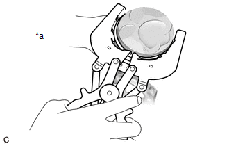
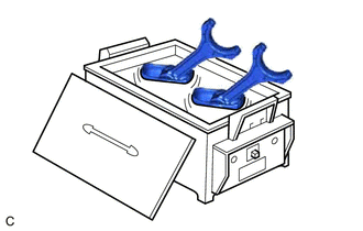
| (2) Gradually heat the piston to approximately 80°C (176°F). CAUTION: Be sure to wear protective gloves. |
|
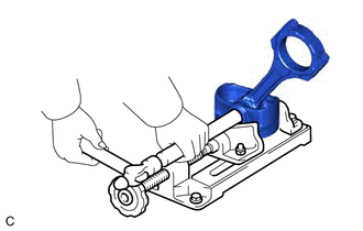
| (3) Using a brass bar and a hammer, lightly tap out the piston pin and remove the connecting rod sub-assembly. HINT:
|
|
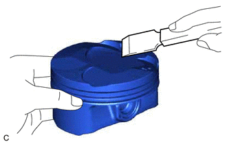
| (c) Using a gasket scraper, remove any carbon from the piston top. NOTICE: Be careful not to scratch the piston. |
|
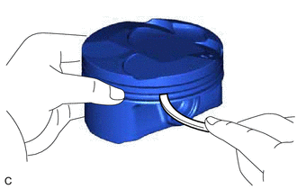
| (d) Using a groove cleaning tool or a broken ring, clean the piston ring grooves. |
|
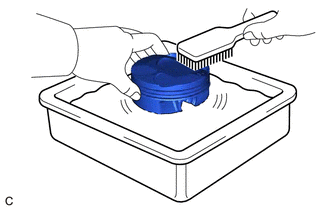
| (e) Using solvent and a brush, thoroughly clean the piston. NOTICE: Do not use a wire brush. |
|
6. REMOVE CRANKSHAFT
| (a) Uniformly loosen and remove the 8 crankshaft bearing cap set bolts and 8 seal washers in several steps in the order shown in the illustration. |
|
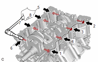
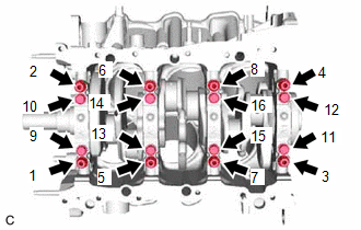
| (b) Uniformly loosen the 16 crankshaft bearing cap set bolts in several steps in the order shown in the illustration. |
|
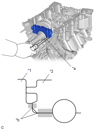
| (c) Using a screwdriver with its tip wrapped with protective tape, pry out the crankshaft bearing caps. Remove the 4 crankshaft bearing caps and 4 lower crankshaft bearings as a set. NOTICE:
|
|
(d) Remove the crankshaft.
7. REMOVE CRANKSHAFT BEARING
(a) Remove the upper crankshaft bearings and lower crankshaft bearings.
HINT:
Arrange the removed parts in such a way that they can be reinstalled to their original locations.
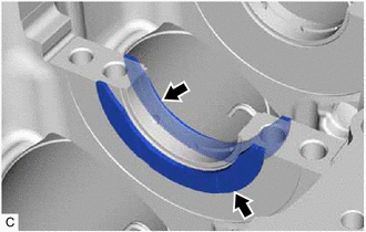
8. REMOVE CRANKSHAFT THRUST WASHER SET
| (a) Remove the crankshaft thrust washer set from the cylinder block sub-assembly. |
|
9. REMOVE NO. 1 OIL NOZZLE SUB-ASSEMBLY
| (a) Using a 5 mm hexagon socket wrench, remove the 3 bolts and 3 No. 1 oil nozzle sub-assemblies. |
|
(b) Check the 3 No. 1 oil nozzle sub-assemblies for damage or clogging.
HINT:
If there is damage or clogs, replace the No. 1 oil nozzle sub-assembly.
READ NEXT:
 Inspection
INSPECTION PROCEDURE 1. INSPECT CONNECTING ROD THRUST CLEARANCE (a) Install the connecting rod cap. Click here (b) Using a dial indicator, measure the thrust clearance while moving the connecting
Replacement
REPLACEMENT PROCEDURE 1. REPLACE STRAIGHT PIN NOTICE: If a straight pin is deformed, replace it. (a) Using a plastic hammer, tap in new straight pins to the cylinder block sub-assembly. *a Front
Reassembly
REASSEMBLY PROCEDURE 1. INSTALL NO. 1 OIL NOZZLE SUB-ASSEMBLY (a) Using a 5 mm hexagon socket wrench, install the 3 No. 1 oil nozzle sub-assemblies to the cylinder block sub-assembly with the 3 bol
SEE MORE:
Hybrid/EV Battery Energy Control Module Monitoring Processor Watchdog / Safety MCU Failure (P060A47)
DESCRIPTION The battery ECU assembly monitors its internal operation and will store these DTCs when it detects an internal malfunction. DTC No. Detection Item DTC Detection Condition Trouble Area MIL Warning Indicate P060A47 Hybrid/EV Battery Energy Control Module Monitoring Proce
Readiness Monitor Drive Pattern
READINESS MONITOR DRIVE PATTERN PURPOSE OF READINESS TESTS
The On-Board Diagnostic (OBD II) system is designed to monitor the performance of emission related components, and indicate any detected abnormalities using DTCs (Diagnostic Trouble Codes). Since various components need to be monitored du
