Lexus ES: Data Signal Circuit between Radio Receiver and Stereo Jack Adapter
DESCRIPTION
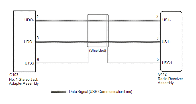
The No. 1 stereo jack adapter assembly sends the sound data signal or image data signal from a USB device to the radio receiver assembly via this circuit.
WIRING DIAGRAM
PROCEDURE
| 1. | CHECK HARNESS AND CONNECTOR (RADIO RECEIVER ASSEMBLY - NO. 1 STEREO JACK ADAPTER ASSEMBLY) |
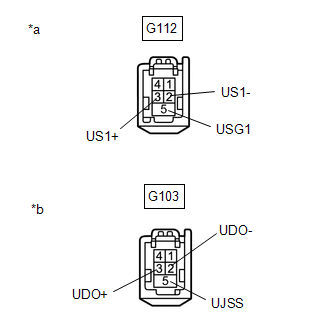
(a) Disconnect the G112 radio receiver assembly connector.
(b) Disconnect the G103 No. 1 stereo jack adapter assembly connector.
| (c) Measure the resistance according to the value(s) in the table below. Standard Resistance:
|
|
| OK |  | PROCEED TO NEXT SUSPECTED AREA SHOWN IN PROBLEM SYMPTOMS TABLE |
.gif)
| NG | | REPAIR OR REPLACE HARNESS OR CONNECTOR |
READ NEXT:
 Diagnostic Trouble Code Chart
DIAGNOSTIC TROUBLE CODE CHART Audio and Visual System DTC No. Detection Item Link B1323 Lost Communication with Haptic Device B1324 Lost Communication with Meter B1326
Display does not Dim when Light Control Switch is Turned ON
DESCRIPTION When the audio and visual system is activated with the light control switch in the tail or head position, before AVC-LAN communication is established, the multi-display assembly dims the d
Does not Play even after Bluetooth Audio Mode is Selected
CAUTION / NOTICE / HINT NOTICE:
Depending on the parts that are replaced during vehicle inspection or maintenance, performing initialization, registration or calibration may be needed. Refer to Pre
SEE MORE:
Reassembly
REASSEMBLY CAUTION / NOTICE / HINT HINT:
Use the same procedure for the RH side and LH side.
The following procedure is for the LH side.
PROCEDURE 1. INSTALL REAR LIGHT PROTECTOR (a) Install a new rear light protector. 2. INSTALL REAR LIGHT GASKET (a) Install a new rear lig
Initialization
INITIALIZATION INITIALIZE LUGGAGE CLOSER MOTOR ASSEMBLY NOTICE: Initialization of the luggage closer motor assembly (luggage compartment door initial position learning) is necessary if the following work procedures are performed while the luggage compartment door is open.
The cable to the negativ
