Lexus ES: Display does not Dim when Light Control Switch is Turned ON
DESCRIPTION
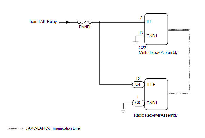
When the audio and visual system is activated with the light control switch in the tail or head position, before AVC-LAN communication is established, the multi-display assembly dims the display according to the illumination signal received via a direct line.
After AVC-LAN communication is established, the multi-display assembly dims the display according to a dimmer signal sent via AVC-LAN communication.
The radio receiver assembly switches between the daytime screen and night screen on the multi-display assembly according to the illumination signal input.
WIRING DIAGRAM
CAUTION / NOTICE / HINT
NOTICE:
Inspect the fuses for circuits related to this system before performing the following procedure.
PROCEDURE
| 1. | CHECK SYMPTOMS |
(a) Check the symptoms that occur by viewing the display.
| Result | Proceed to |
|---|---|
| There is a delay until the display dims after the audio and visual system is activated with the light control switch in the tail or head position. | A |
| The display dims for a moment and then becomes bright after the audio and visual system is activated with the light control switch in the tail or head position. | B |
| When the light control switch is set to the tail or head position, the display dims but does not switch to the night screen. | |
| When the light control switch is set to the tail or head position, the display neither dims nor switches to the night screen. | C |
HINT:
- When the audio and visual system is activated with the light control switch in the tail or head position, before AVC-LAN communication is established, the multi-display assembly dims the display according to the illumination signal received via a direct line.
- After AVC-LAN communication is established, the multi-display assembly dims the display according to a dimmer signal sent via AVC-LAN communication.
- The radio receiver assembly switches between the daytime screen and night screen on the multi-display assembly according to the illumination signal input.
| B |  | GO TO STEP 3 |
| C | | GO TO LIGHTING SYSTEM |
|

| 2. | CHECK HARNESS AND CONNECTOR (ILLUMINATION SIGNAL) |
(a) Disconnect the G22 multi-display assembly connector.
(b) Measure the resistance according to the value(s) in the table below.
Standard Resistance:
| Tester Connection | Condition | Specified Condition |
|---|---|---|
| G22-13 (GND1) - Body ground | Always | Below 1 Ω |
(c) Measure the voltage according to the value(s) in the table below.
Standard Voltage:
| Tester Connection | Condition | Specified Condition |
|---|---|---|
| G22-2 (ILL) - G22-13 (GND1) | Light control switch in tail or head position | 11 to 14 V |
| OK | | PROCEED TO NEXT SUSPECTED AREA SHOWN IN PROBLEM SYMPTOMS TABLE |
.gif)
| NG | | REPAIR OR REPLACE HARNESS OR CONNECTOR |
| 3. | CHECK IMAGE QUALITY SETTING |
(a) Turn the light control switch to the tail or head position.
(b) Check that the daytime screen setting on the display adjustment screen is set to on.
| Result | Proceed to |
|---|---|
| Daytime screen setting is set to on. | A |
| Daytime screen setting is set to off. | B |
| A | | CHANGE DAYTIME SCREEN SETTING TO OFF |
|
| 4. | CHECK VEHICLE SIGNAL (OPERATION CHECK) |
| (a) Enter the "Vehicle Signal Check Mode" screen. Refer to Check Vehicle Signal in Operation Check. Click here |
|
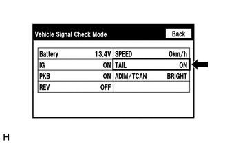
(b) Check that the display changes between ON and OFF according to the light control switch operation.
OK:
| Light Control Switch | Display |
|---|---|
| Tail or head | ON |
| Off or AUTO | OFF |
HINT:
- The display is updated once per second. It is normal for the display to lag behind the actual switch operation.
- Make sure to move the vehicle to a bright area before performing an operation check with the light control switch in the AUTO position.
| OK | | PROCEED TO NEXT SUSPECTED AREA SHOWN IN PROBLEM SYMPTOMS TABLE |
|
| 5. | CHECK HARNESS AND CONNECTOR (ILLUMINATION SIGNAL) |
(a) Disconnect the G4 and G6 radio receiver assembly connectors.
(b) Measure the resistance according to the value(s) in the table below.
Standard Resistance:
| Tester Connection | Condition | Specified Condition |
|---|---|---|
| G6-1 (GND1) - Body ground | Always | Below 1 Ω |
(c) Measure the voltage according to the value(s) in the table below.
Standard Voltage:
| Tester Connection | Condition | Specified Condition |
|---|---|---|
| G4-15 (ILL+) - G6-1 (GND1) | Light control switch in tail or head position | 11 to 14 V |
| OK | | PROCEED TO NEXT SUSPECTED AREA SHOWN IN PROBLEM SYMPTOMS TABLE |
| NG | | REPAIR OR REPLACE HARNESS OR CONNECTOR |
READ NEXT:
 Does not Play even after Bluetooth Audio Mode is Selected
CAUTION / NOTICE / HINT NOTICE:
Depending on the parts that are replaced during vehicle inspection or maintenance, performing initialization, registration or calibration may be needed. Refer to Pre
Dtc Check / Clear
DTC CHECK / CLEAR CHECK DTC (CHECK USING TECHSTREAM) (a) Connect the Techstream to the DLC3. (b) Turn the engine switch on (IG) and wait for 90 seconds. (c) Turn the Techstream on. (d) Enter the follo
Freeze Frame Data
FREEZE FRAME DATA CHECK FREEZE FRAME DATA (a) Connect the Techstream to the DLC3. (b) Turn the engine switch on (IG). (c) Turn the Techstream on. (d) Enter the following menus: Body Electrical / Navig
SEE MORE:
Installation
INSTALLATION PROCEDURE 1. INSTALL FUEL TANK PRESSURE SENSOR (VAPOR PRESSURE SENSOR) (a) Push the fuel tank pressure sensor (vapor pressure sensor) onto the fuel tank assembly, then install the tube joint clip. NOTICE:
Check that there are no scratches or foreign matter around the connecting
Brake Booster Pump Motor on Time Abnormally Long (C1252,C1253)
DESCRIPTION The skid control ECU (brake booster with master cylinder assembly) detects decreases in the accumulator pressure according to the data from the accumulator pressure sensor, and then starts and stops the pump motor by operating the motor relay. DTC No. Detection Item INF Code DTC
