Lexus ES: Cylinder 1 Injector "B" Circuit Open (P21CF13,P21D013-P21D413)
DESCRIPTION
The D-4S system has two injection systems. One is an in-cylinder direct injection system that directly injects pressurized fuel into the combustion chamber. The other is an intake port injection system. The ECM determines the percentage of direct injection and port injection necessary in accordance with the engine speed and load.
| DTC No. | Detection Item | DTC Detection Condition | Trouble Area | MIL | Memory | Note |
|---|---|---|---|---|---|---|
| P21CF13 | Cylinder 1 Injector "B" Circuit Open | Current is not applied to the injector 10 times or more with the engine running (1 trip detection logic). |
| Comes on | DTC stored | SAE Code: P21CF |
| P21D013 | Cylinder 2 Injector "B" Circuit Open | Current is not applied to the injector 10 times or more with the engine running (1 trip detection logic). |
| Comes on | DTC stored | SAE Code: P21D0 |
| P21D113 | Cylinder 3 Injector "B" Circuit Open | Current is not applied to the injector 10 times or more with the engine running (1 trip detection logic). |
| Comes on | DTC stored | SAE Code: P21D1 |
| P21D213 | Cylinder 4 Injector "B" Circuit Open | Current is not applied to the injector 10 times or more with the engine running (1 trip detection logic). |
| Comes on | DTC stored | SAE Code: P21D2 |
| P21D313 | Cylinder 5 Injector "B" Circuit Open | Current is not applied to the injector 10 times or more with the engine running (1 trip detection logic). |
| Comes on | DTC stored | SAE Code: P21D3 |
| P21D413 | Cylinder 6 Injector "B" Circuit Open | Current is not applied to the injector 10 times or more with the engine running (1 trip detection logic). |
| Comes on | DTC stored | SAE Code: P21D4 |
MONITOR DESCRIPTION
The ECM monitors the injection control of the port fuel injector assemblies. If a malfunction is detected in a port fuel injector assembly circuit, the ECM cancels the injection control for the corresponding cylinder, illuminates the MIL and stores a DTC.
MONITOR STRATEGY
| Related DTCs | P21CF: Port injector (cylinder 1) circuit/open P21D0: Port injector (cylinder 2) circuit/open P21D1: Port injector (cylinder 3) circuit/open P21D2: Port injector (cylinder 4) circuit/open P21D3: Port injector (cylinder 5) circuit/open P21D4: Port injector (cylinder 6) circuit/open |
| Required Sensors/Components (Main) | Port fuel injector assembly (cylinder 1 to 6) |
| Required Sensors/Components (Related) | - |
| Frequency of Operation | Continuous |
| Duration | 10 times |
| MIL Operation | Immediate |
| Sequence of Operation | None |
TYPICAL ENABLING CONDITIONS
| Monitor runs whenever the following DTCs are not stored | None |
| All of the following conditions are met | - |
| Battery voltage | 8 V or higher |
| Fuel cut | Off |
| Synchronous injection | Operating |
| Engine switch | On (IG) |
| Either of the following conditions is met | Condition A or B |
| A. Engine | Running |
| B. Starter | On |
| Injection time | Higher than 0 second |
TYPICAL MALFUNCTION THRESHOLDS
| Confirmed injection signal | No signal |
CONFIRMATION DRIVING PATTERN
HINT:
-
After repair has been completed, clear the DTC and then check that the vehicle has returned to normal by performing the following All Readiness check procedure.
Click here
.gif)
-
When clearing the permanent DTCs, refer to the "CLEAR PERMANENT DTC" procedure.
Click here
- Connect the Techstream to the DLC3.
- Turn the engine switch on (IG).
- Turn the Techstream on.
- Clear the DTCs (even if no DTCs are stored, perform the clear DTC procedure).
- Turn the engine switch off and wait for at least 30 seconds.
- Start the engine [A].
- Idle the engine for 3 minutes or more [B].
- Turn the Techstream on.
- Enter the following menus: Powertrain / Engine / Trouble Codes [C].
-
Read the DTCs [B].
HINT:
- If a pending DTC is output, the system is malfunctioning.
- If a pending DTC is not output, perform the following procedure.
- Enter the following menus: Powertrain / Engine / Utility / All Readiness.
- Input the DTC: P21CF13, P21D013, P21D113, P21D213, P212313 or P212413.
-
Check the DTC judgment result.
Techstream Display
Description
NORMAL
- DTC judgment completed
- System normal
ABNORMAL
- DTC judgment completed
- System abnormal
INCOMPLETE
- DTC judgment not completed
- Perform driving pattern after confirming DTC enabling conditions
HINT:
- If the judgment result is NORMAL, the system is normal.
- If the judgment result is ABNORMAL, the system has a malfunction.
- If the judgment result is INCOMPLETE, perform steps [B] through [C] again.
-
[A] to [C]: Normal judgment procedure.
The normal judgment procedure is used to complete DTC judgment and also used when clearing permanent DTCs.
- When clearing the permanent DTCs, do not disconnect the cable from the battery terminal or attempt to clear the DTCs during this procedure, as doing so will clear the universal trip and normal judgment histories.
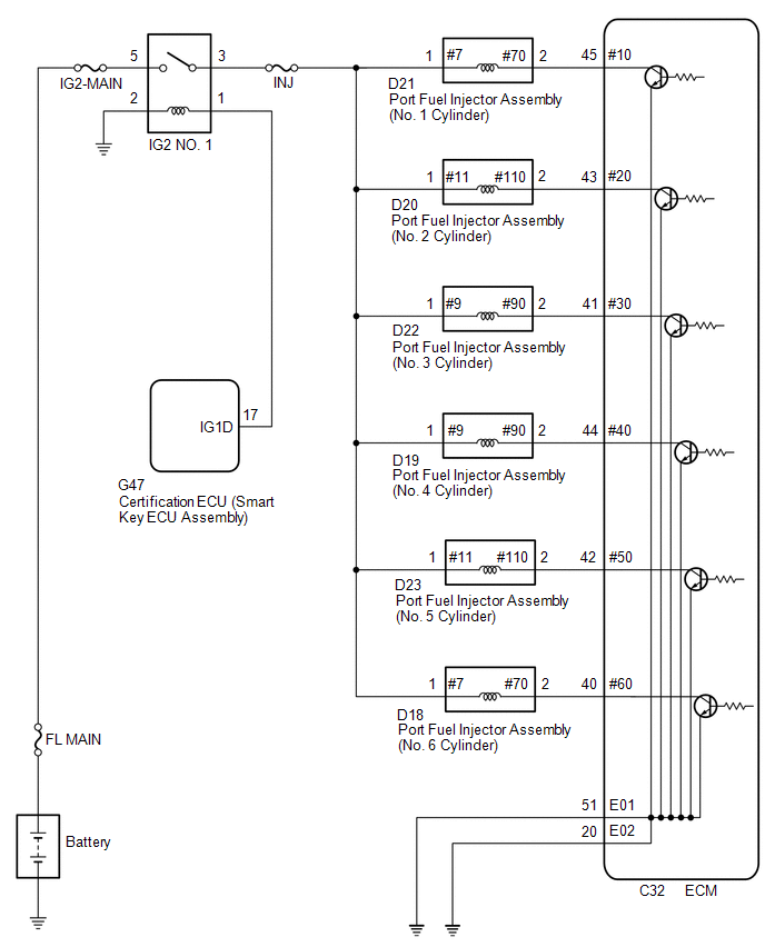
WIRING DIAGRAM
CAUTION / NOTICE / HINT
NOTICE:
Inspect the fuses for circuits related to this system before performing the following procedure.
HINT:
Read freeze frame data using the Techstream. The ECM records vehicle and driving condition information as freeze frame data the moment a DTC is stored. When troubleshooting, freeze frame data can help determine if the vehicle was moving or stationary, if the engine was warmed up or not, if the air fuel ratio was lean or rich, and other data from the time the malfunction occurred.
PROCEDURE
| 1. | CHECK DTCS OUTPUT (IN ADDITION TO DTC P21CF13, P21D013, P21D113, P21D213, P21D313 OR P21D413) |
(a) Connect the Techstream to the DLC3.
(b) Turn the engine switch on (IG).
(c) Turn the Techstream on.
(d) Enter the following menus: Powertrain / Engine / Trouble Codes.
(e) Read the DTCs.
Powertrain > Engine > Trouble Codes| Result | Proceed to |
|---|---|
| P21CF13, P21D013, P21D113, P21D213, P21D313 or P21D413 is output | A |
| P21CF13, P21D013, P21D113, P22D213, P21D313 and P21D413 are output | B |
| B | .gif) | REPAIR OR REPLACE HARNESS OR CONNECTOR (IG2 NO. 1 RELAY - PORT FUEL INJECTOR ASSEMBLY) |
|
.gif)
| 2. | CHECK TERMINAL VOLTAGE (POWER SOURCE OF PORT FUEL INJECTOR ASSEMBLY) |
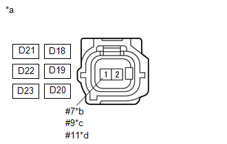
| *a | Front view of wire harness connector (to Port Fuel Injector Assembly) |
| *b | No. 1 Cylinder or No. 6 Cylinder |
| *c | No. 3 Cylinder or No. 4 Cylinder |
| *d | No. 2 Cylinder or No. 5 Cylinder |
(a) Disconnect the port fuel injector assembly connector.
(b) Turn the engine switch on (IG).
(c) Measure the voltage according to the value(s) in the table below
Standard Voltage:
| Tester Connection | Condition | Specified Condition |
|---|---|---|
| D21-1 (#7) - Body ground | Engine switch on (IG) | 11 to 14 V |
| D18-1 (#7) - Body ground | Engine switch on (IG) | 11 to 14 V |
| D22-1 (#9) - Body ground | Engine switch on (IG) | 11 to 14 V |
| D19-1 (#9) - Body ground | Engine switch on (IG) | 11 to 14 V |
| D23-1 (#11) - Body ground | Engine switch on (IG) | 11 to 14 V |
| D20-1 (#11) - Body ground | Engine switch on (IG) | 11 to 14 V |
| NG | | REPAIR OR REPLACE HARNESS OR CONNECTOR (IG2 NO. 1 RELAY - PORT FUEL INJECTOR ASSEMBLY) |
|
| 3. | CHECK HARNESS AND CONNECTOR (PORT FUEL INJECTOR ASSEMBLY - ECM) |
(a) Disconnect the ECM connector.
(b) Disconnect the port fuel injector assembly connector.
(c) Measure the resistance according to the value(s) in the table below.
Standard Resistance:
| Tester Connection | Condition | Specified Condition |
|---|---|---|
| D21-2 (#70) - C32-45 (#10) | Always | Below 1 Ω |
| D18-2 (#70) - C32-40 (#60) | Always | Below 1 Ω |
| D22-2 (#90) - C32-41 (#30) | Always | Below 1 Ω |
| D19-2 (#90) - C32-44 (#40) | Always | Below 1 Ω |
| D23-2 (#110) - C32-42 (#50) | Always | Below 1 Ω |
| D20-2 (#110) - C32-43 (#20) | Always | Below 1 Ω |
| D21-2 (#70) or C32-45 (#10) - Body ground and other terminals | Always | 10 kΩ or higher |
| D18-2 (#70) or C32-40 (#60) - Body ground and other terminals | Always | 10 kΩ or higher |
| D22-2 (#90) or C32-41 (#30) - Body ground and other terminals | Always | 10 kΩ or higher |
| D19-2 (#90) or C32-44 (#40) - Body ground and other terminals | Always | 10 kΩ or higher |
| D23-2 (#110) or C32-42 (#50) - Body ground and other terminals | Always | 10 kΩ or higher |
| D20-2 (#110) or C32-43 (#20) - Body ground and other terminals | Always | 10 kΩ or higher |
| NG | | REPAIR OR REPLACE HARNESS OR CONNECTOR |
|
| 4. | INSPECT PORT FUEL INJECTOR ASSEMBLY (RESISTANCE) |
(a) Inspect the port fuel injector assembly.
Click here
HINT:
Perform "Inspection After Repair" after replacing the port fuel injector assembly.
Click here
| OK | | REPLACE ECM |
| NG | | REPLACE PORT FUEL INJECTOR ASSEMBLY |
READ NEXT:
 A/F (O2) Sensor Positive Current Control Bank 1 Sensor 1 Circuit Short to Ground (P223711,...,P225412)
DESCRIPTION Refer to DTC P219519. Click here HINT: Although the DTC titles say O2 sensor, these DTCs relate to the air fuel ratio sensor. DTC No. Detection Item DTC Detection Condition Trou
Evaporative Emission System Switching Valve Control Circuit Actuator Stuck Off (P24187F)
DTC SUMMARY DTC No. Detection Item DTC Detection Condition Trouble Area MIL Memory Note P24187F Evaporative Emission System Switching Valve Control Circuit Actuator Stuck Off Fo
ECM/PCM Engine Off Timer Performance Signal Invalid (P261029,P261093)
DTC SUMMARY DTC No. Detection Item DTC Detection Condition Trouble Area MIL Memory Note P261029 ECM/PCM Engine Off Timer Performance Signal Invalid ECM internal malfunction EC
SEE MORE:
ECU Malfunction (C1611)
DESCRIPTION This DTC is stored if the rear television camera assembly judges that there is an internal malfunction as a result of its self check. HINT: The rear television camera assembly stores different types of information during initialization. If the rear television camera assembly cannot read
Precaution
PRECAUTION PRECAUTIONS FOR INSPECTING HYBRID CONTROL SYSTEM (a) Before the following operations are conducted, take precautions to prevent electric shock by turning the power switch off, wearing insulated gloves, and removing the service plug grip from HV battery.
Inspecting the high-voltage syst
