Lexus ES: Throttle/Pedal Position Sensor/Switch "B" Circuit Short to Battery or Open (P022015)
DESCRIPTION
Refer to DTC P012011.
Click here .gif)
| DTC No. | Detection Item | DTC Detection Condition | Trouble Area | MIL | Memory | Note |
|---|---|---|---|---|---|---|
| P022015 | Throttle/Pedal Position Sensor/Switch "B" Circuit Short to Battery or Open | The output voltage of VTA2 is higher than 4.75 V, and VTA1 is less than 2.367 V for 2 seconds or more (1 trip detection logic). |
| Comes on | DTC stored | SAE Code: P0223 |
MONITOR DESCRIPTION
The ECM uses the throttle position sensor to monitor the throttle valve opening angle. If the VTA2 terminal voltage is higher than the threshold, the ECM will illuminate the MIL and store this DTC.
MONITOR STRATEGY
| Related DTCs | P0223: Throttle position sensor 2 range check (high voltage) |
| Required Sensors/Components (Main) | Throttle position sensor |
| Required Sensors/Components (Related) | - |
| Frequency of Operation | Continuous |
| Duration | 2 seconds |
| MIL Operation | Immediate |
| Sequence of Operation | None |
TYPICAL ENABLING CONDITIONS
| Monitor runs whenever the following DTCs are not stored | None |
| Both of the following conditions are met | - |
| Auxiliary battery voltage | 8 V or higher |
| Power switch | On (IG) |
TYPICAL MALFUNCTION THRESHOLDS
| VTA2 voltage when VTA1 less than 2.367 V | Higher than 4.75 V |
CONFIRMATION DRIVING PATTERN
HINT:
-
After repair has been completed, clear the DTC and then check that the vehicle has returned to normal by performing the following All Readiness check procedure.
Click here
-
When clearing the permanent DTCs, refer to the "CLEAR PERMANENT DTC" procedure.
Click here
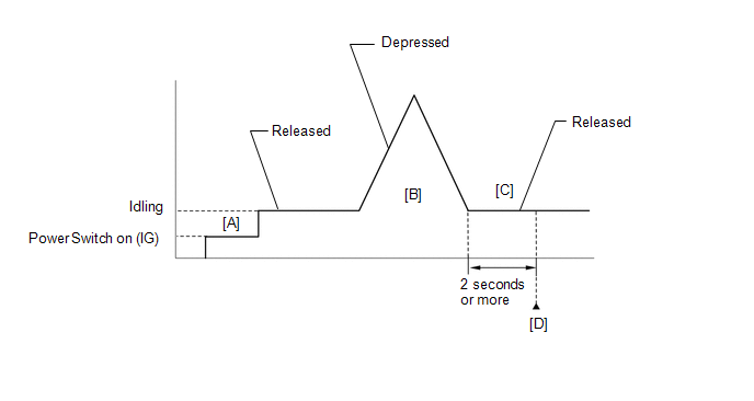
- Connect the Techstream to the DLC3.
- Turn the power switch on (IG).
- Turn the Techstream on.
- Clear the DTCs (even if no DTCs are stored, perform the clear DTC procedure).
- Turn the power switch off and wait for at least 30 seconds.
- Turn the power switch on (IG) [A].
- Turn the Techstream on.
- Put the engine in Inspection Mode (Maintenance Mode).
- Start the engine.
-
With the vehicle stationary, fully depress and release the accelerator pedal [B].
HINT:
During charge control, the engine speed is set at idle. Therefore, the engine speed will not increase when the accelerator pedal is depressed. In this case, perform step [B] after charge control has completed.
- Idle the engine for 2 seconds or more [C].
- Enter the following menus: Powertrain / Engine / Trouble Codes [D].
-
Read the pending DTCs.
HINT:
- If a pending DTC is output, the system is malfunctioning.
- If a pending DTC is not output, perform the following procedure.
- Enter the following menus: Powertrain / Engine / Utility / All Readiness.
- Input the DTC: P022015.
-
Check the DTC judgment result.
Techstream Display
Description
NORMAL
- DTC judgment completed
- System normal
ABNORMAL
- DTC judgment completed
- System abnormal
INCOMPLETE
- DTC judgment not completed
- Perform driving pattern after confirming DTC enabling conditions
HINT:
- If the judgment result is NORMAL, the system is normal.
- If the judgment result is ABNORMAL, the system is malfunctioning.
- If the judgment result is INCOMPLETE, perform steps [B] through [D] again.
-
[A] to [D]: Normal judgment procedure.
The normal judgment procedure is used to complete DTC judgment and also used when clearing permanent DTCs.
- When clearing the permanent DTCs, do not disconnect the cable from the auxiliary battery terminal or attempt to clear the DTCs during this procedure, as doing so will clear the universal trip and normal judgment histories.
FAIL-SAFE
When this DTC is stored, the ECM enters fail-safe mode. During fail-safe mode, the ECM cuts the current to the throttle actuator, and the throttle valve is returned to a 7.5° throttle valve opening angle by the return spring. The ECM then adjusts the engine output, by controlling the fuel injection (intermittent fuel cut) and ignition timing, in accordance with the engine torque request signal sent from the hybrid vehicle control ECU assembly, to allow the vehicle to continue being driven at a minimal speed. If the accelerator pedal is depressed firmly and gently, the vehicle can be driven slowly.
Fail-safe mode continues until a pass condition is detected, and the power switch is turned off.
WIRING DIAGRAM
Refer to DTC P012011.
Click here
CAUTION / NOTICE / HINT
NOTICE:
-
Vehicle Control History may be stored in the hybrid vehicle control ECU assembly if the engine is malfunctioning. Certain vehicle condition information is recorded when Vehicle Control History is stored. Reading the vehicle conditions recorded in both the Freeze Frame Data and Vehicle Control History can be useful for troubleshooting.
Click here
(Select Powertrain in Health Check and then check the time stamp data.)
Click here
-
If any "Engine Malfunction" Vehicle Control History item has been stored in the hybrid vehicle control ECU assembly, make sure to clear it. However, as all Vehicle Control History items are cleared simultaneously, if any Vehicle Control History items other than "Engine Malfunction" are stored, make sure to perform any troubleshooting for them before clearing Vehicle Control History.
Click here
HINT:
Read Freeze Frame Data using the Techstream. The ECM records vehicle and driving condition information as Freeze Frame Data the moment a DTC is stored. When troubleshooting, Freeze Frame Data can help determine if the vehicle was moving or stationary, if the engine was warmed up or not, if the air fuel ratio was lean or rich, and other data from the time the malfunction occurred.
PROCEDURE
| 1. | CHECK HARNESS AND CONNECTOR (THROTTLE POSITION SENSOR - ECM) |
(a) Disconnect the throttle body with motor assembly connector.
(b) Disconnect the ECM connector.
(c) Measure the resistance according to the value(s) in the table below.
Standard Resistance:
| Tester Connection | Condition | Specified Condition |
|---|---|---|
| C57-3 (VTA2) - C88-87 (VTA2) | Always | Below 1 Ω |
| C57-2 (VC) or C88-109 (VCTA) - Other terminals | Always | 10 kΩ or higher |
| C57-3 (VTA2) or C88-87 (VTA2) - Other terminals | Always | 10 kΩ or higher |
| NG | .gif) | REPAIR OR REPLACE HARNESS OR CONNECTOR |
|
.gif)
| 2. | CHECK TERMINAL VOLTAGE (POWER SOURCE OF THROTTLE POSITION SENSOR) |
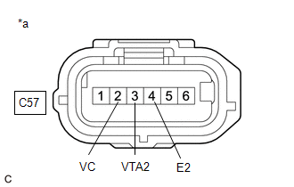
| *a | Front view of wire harness connector (to Throttle Body with Motor Assembly) |
(a) Disconnect the throttle body with motor assembly connector.
(b) Turn the power switch on (IG).
(c) Measure the voltage according to the value(s) in the table below.
Standard Voltage:
| Tester Connection | Condition | Specified Condition |
|---|---|---|
| C57-2 (VC) - C57-4 (E2) | Power switch on (IG) | 4.5 to 5.5 V |
| C57-3 (VTA2) - C57-4 (E2) | Power switch on (IG) | 3.0 to 5.0 V |
| NG | | REPLACE ECM |
|
| 3. | CHECK HARNESS AND CONNECTOR (RESISTANCE OF ECM) |
(a) Disconnect the throttle body with motor assembly connector.
(b) Measure the resistance according to the value(s) in the table below.
Standard Resistance:
| Tester Connection | Condition | Specified Condition |
|---|---|---|
| C57-2 (VC) - C57-3 (VTA2) | Power switch off | 190 to 210 kΩ |
| NG | | REPLACE ECM |
|
| 4. | READ VALUE USING TECHSTREAM (THROTTLE POSITION SENSOR NO.2 VOLTAGE) |
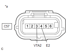
| *a | Front view of wire harness connector (to Throttle Body with Motor Assembly) |
(a) Disconnect the throttle body with motor assembly connector.
(b) Connect the Techstream to the DLC3.
(c) Turn the power switch on (IG).
(d) Turn the Techstream on.
(e) Enter the following menus: Powertrain / Engine / Data List / Throttle Position Sensor No.2 Voltage.
Powertrain > Engine > Data List| Tester Display |
|---|
| Throttle Position Sensor No.2 Voltage |
(f) According to the display on the Techstream, read the Data List.
HINT:
Use the snapshot function to record the value displayed or make a note of it.
(g) Turn the power switch off.
(h) Turn the Techstream off.
(i) Connect terminals 3 (VTA2) and 4 (E2) of the throttle body with motor assembly connector on the wire harness side.
NOTICE:
If the VTA2 terminal voltage or the resistance between VTA2 and E2 is abnormal and terminals 3 (VTA2) and 4 (E2) of the throttle body with motor assembly connector are connected, excessive current may flow through the circuit. In this case, do not connect the terminals.
(j) Turn the power switch on (IG).
(k) Turn the Techstream on.
(l) Enter the following menus: Powertrain / Engine / Data List / Throttle Position Sensor No.2 Voltage.
Powertrain > Engine > Data List| Tester Display |
|---|
| Throttle Position Sensor No.2 Voltage |
(m) Compare the vehicle of the Data List item Throttle Position Sensor No.2 Voltage after the circuit is shorted to the value when the throttle body with motor assembly connector was connected.
| Result | Proceed to |
|---|---|
| Changes from higher than 4.75 V to less than 2.05 V | A |
| Does not change from higher than 4.75 V | B |
HINT:
Perform "Inspection After Repair" after replacing the throttle body with motor assembly.
Click here
| A | | REPLACE THROTTLE BODY WITH MOTOR ASSEMBLY |
| B | | REPLACE ECM |
READ NEXT:
 Random/Multiple Cylinder Misfire Detected (P030000,P030027,P030085-P030400)
DESCRIPTION When the engine misfires, high concentrations of hydrocarbons (HC) enter the exhaust gas. Extremely high hydrocarbon concentration levels can cause an increase in exhaust emission levels.
Knock Sensor 1 Bank 1 or Single Sensor Circuit Short to Ground (P032511)
DESCRIPTION A flat-type knock control sensor (non-resonant type) has a structure that can detect vibrations between approximately 5 and 23 kHz. The knock control sensor is fitted onto the engine block
Knock Sensor 1 Bank 1 or Single Sensor Circuit Short to Battery or Open (P032515)
DESCRIPTION Refer to DTC P032511. Click here HINT: When DTC P032515 is stored, the ECM enters fail-safe mode. During fail-safe mode, the ignition timing is delayed to its maximum retardation. Fail-s
SEE MORE:
Blind Spot Monitor Slave Module Beam Axis Inspection Incomplete (C1ABC)
DESCRIPTION This DTC is stored when a beam axis inspection has not been performed for the blind spot monitor sensor LH. HINT: This DTC is always stored after replacing a blind spot monitor sensor. The purpose of this DTC is to ensure that a beam axis inspection is performed. Completing the beam axis
System Description
SYSTEM DESCRIPTION GENERAL (a) This system has a rear television camera assembly mounted on the luggage compartment door to display an image of the area behind the vehicle on the multi-display. The multi-display also shows a composite view consisting of the area behind the vehicle and parking guide
