Lexus ES: Crankshaft Position Sensor
Components
COMPONENTS
ILLUSTRATION
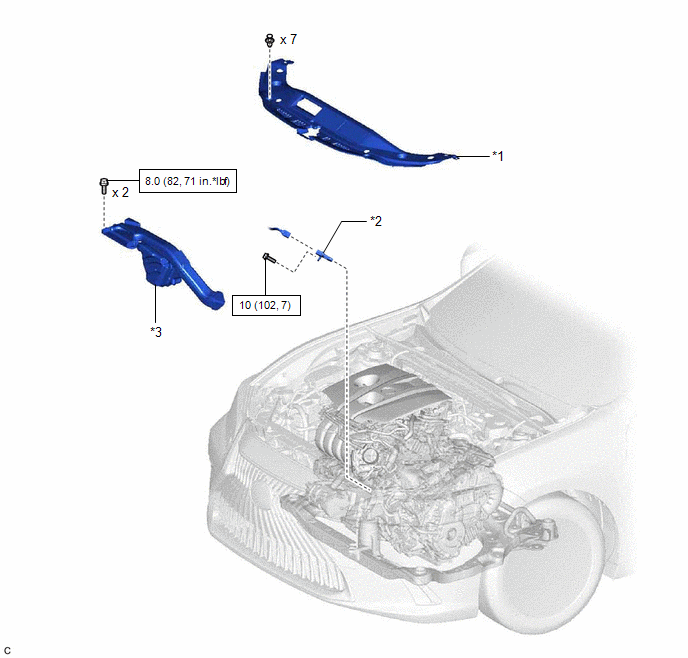
| *1 | COOL AIR INTAKE DUCT SEAL | *2 | CRANKSHAFT POSITION SENSOR |
| *3 | INLET AIR CLEANER ASSEMBLY | - | - |
.png) | N*m (kgf*cm, ft.*lbf): Specified torque | - | - |
Removal
REMOVAL
CAUTION / NOTICE / HINT
NOTICE:
This procedure includes the removal of small-head bolts. Refer to Small-Head Bolts of Basic Repair Hint to identify the small-head bolts.
Click here .gif)
PROCEDURE
1. REMOVE COOL AIR INTAKE DUCT SEAL
Click here
2. REMOVE INLET AIR CLEANER ASSEMBLY
Click here
3. REMOVE CRANKSHAFT POSITION SENSOR
| (a) Disconnect the crankshaft position sensor connector. |
|
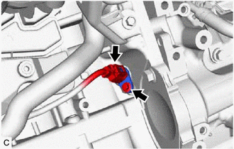
(b) Using an 8 mm socket wrench, remove the bolt and crankshaft position sensor from the cylinder block sub-assembly.
NOTICE:
If the crankshaft position sensor has been struck or dropped, replace it.
Installation
INSTALLATION
CAUTION / NOTICE / HINT
NOTICE:
This procedure includes the installation of small-head bolts. Refer to Small-Head Bolts of Basic Repair Hint to identify the small-head bolts.
Click here .gif)
PROCEDURE
1. INSTALL CRANKSHAFT POSITION SENSOR
(a) Apply a light coat of engine oil to the O-ring of the crankshaft position sensor.
NOTICE:
If reusing the crankshaft position sensor, be sure to inspect the O-ring.
(b) Using an 8 mm socket wrench, install the crankshaft position sensor to the cylinder block sub-assembly with the bolt.
Torque:
10 N·m {102 kgf·cm, 7 ft·lbf}
NOTICE:
- If the crankshaft position sensor has been struck or dropped, replace it.
- Make sure that the O-ring is not cracked or moved out of place when installing the crankshaft position sensor.
(c) Connect the crankshaft position sensor connector.
2. INSTALL INLET AIR CLEANER ASSEMBLY
Click here
3. INSTALL COOL AIR INTAKE DUCT SEAL
Click here
READ NEXT:
 Components
COMPONENTS ILLUSTRATION *1 ECM *2 NO. 1 ECM BRACKET *3 NO. 2 ECM BRACKET - - N*m (kgf*cm, ft.*lbf): Specified torque - -
Removal
REMOVAL CAUTION / NOTICE / HINT The necessary procedures (adjustment, calibration, initialization or registration) that must be performed after parts are removed and installed, or replaced during ECM
SEE MORE:
Inspection
INSPECTION PROCEDURE 1. INSPECT FLOW SHUTTING VALVE (WATER BY-PASS HOSE ASSEMBLY) (a) Measure the resistance according to the value(s) in the table below. Standard Resistance: Tester Connection Condition Specified Condition 1 - 2 20°C (68°F) 22 to 28 Ω If the result is not a
Open circuit in Power source circuit (C13A0,C13A5,C13B0)
DESCRIPTION DTC No. Detection Item DTC Detection Condition Trouble Area Memory Note C13A0 Open circuit in Power source circuit Both of following conditions are met:
Power switch on (IG) or electric parking brake switch assembly pushed to lock side with power switch off.
Par
