Lexus ES: Cooling System
On-vehicle Inspection
ON-VEHICLE INSPECTION
CAUTION / NOTICE / HINT
CAUTION:
Do not remove the radiator cap sub-assembly while the engine and radiator assembly are still hot. Pressurized, hot engine coolant and steam may be released and cause serious burns.
.png)
PROCEDURE
1. INSPECT FOR COOLANT LEAK
CAUTION:
Do not remove the radiator cap sub-assembly while the engine and radiator assembly are still hot. Pressurized, hot engine coolant and steam may be released and cause serious burns.
(a) Remove the radiator cap sub-assembly.
| (b) Fill the radiator assembly with engine coolant, and then install a radiator cap tester. |
|
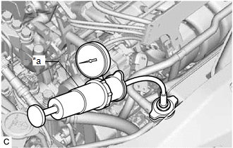
(c) Warm up the engine.
(d) Pump the radiator cap tester to 103 kPa (1.1 kgf/cm2, 15 psi), and then check that the pressure does not drop.
- If the pressure drops, check the hoses, radiator assembly and engine water pump assembly (water inlet housing) for leaks.
- If there are no signs of external engine coolant leaks, check the heater core, cylinder block sub-assembly and cylinder head sub-assembly.
(e) Remove the radiator cap tester.
(f) Install the radiator cap sub-assembly.
2. INSPECT ENGINE COOLANT LEVEL IN RESERVOIR TANK
| (a) Check that the engine coolant level is between the L line and F line when the engine is cold. If the engine coolant level is low, check for leaks and add engine coolant to the F line. NOTICE: Do not substitute plain water for engine coolant. |
|
.png)
3. INSPECT ENGINE COOLANT QUALITY
CAUTION:
Do not remove the radiator cap sub-assembly while the engine and radiator assembly are still hot. Pressurized, hot engine coolant and steam may be released and cause serious burns.
(a) Remove the radiator cap sub-assembly.
(b) Check if there are any excessive deposits of rust or scale around the radiator cap sub-assembly and water filler hole. Also, the engine coolant should be free of oil.
If excessively dirty, replace the engine coolant.
(c) Install the radiator cap sub-assembly.
READ NEXT:
 Components
COMPONENTS ILLUSTRATION *1 FRONT FENDER APRON SEAL LH *2 FRONT WHEEL OPENING EXTENSION PAD LH *3 FRONT WHEEL OPENING EXTENSION PAD RH *4 NO. 1 ENGINE UNDER COVER *5 NO. 2 ENG
Inspection
INSPECTION PROCEDURE 1. INSPECT FLOW SHUTTING VALVE (NO. 1 WATER BY-PASS HOSE) (a) Measure the resistance according to the value(s) in the table below. Standard Resistance: Tester Connection Con
SEE MORE:
Electric Parking Brake Switch
ComponentsCOMPONENTS ILLUSTRATION *1 ELECTRIC PARKING BRAKE SWITCH ASSEMBLY *2 LOWER INSTRUMENT PANEL *3 INSTRUMENT PANEL FINISH PANEL END - - InspectionINSPECTION PROCEDURE 1. INSPECT ELECTRIC PARKING BRAKE SWITCH ASSEMBLY (a) Check the resistance. (1) Measure the resist
Rear Power Window LH Auto Up / Down Function does not Operate with Rear Power Window Switch LH
DESCRIPTION If the manual up and down functions operate normally but the auto up and down functions do not, the power window control system may be in fail-safe mode. If power window initialization has not been performed, the auto up and down functions will not operate. Click here WIRING DIAGRAM C
