Lexus ES: Components
COMPONENTS
ILLUSTRATION
.png)
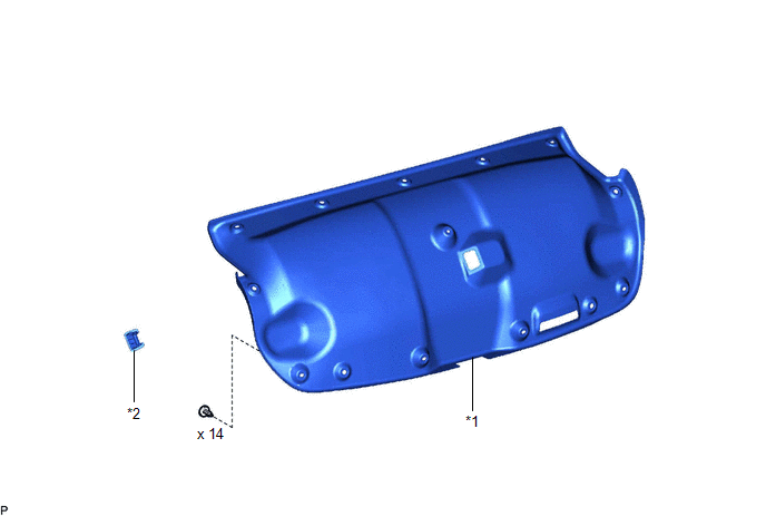
| *1 | LUGGAGE COMPARTMENT FLOOR MAT | *2 | SPARE WHEEL COVER TRAY |
ILLUSTRATION
.png)
| *1 | REAR FLOOR FINISH PLATE | *2 | LUGGAGE HOLD BELT STRIKER ASSEMBLY |
ILLUSTRATION
| *1 | LUGGAGE COMPARTMENT DOOR COVER | *2 | LUGGAGE LOCK CONTROL CABLE PLATE |
ILLUSTRATION
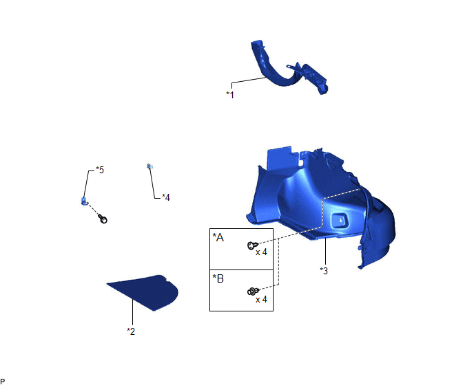
| *A | for Type A | *B | for Type B |
| *1 | LUGGAGE COMPARTMENT DOOR HINGE COVER RH | *2 | LUGGAGE COMPARTMENT TRIM COVER RH |
| *3 | LUGGAGE COMPARTMENT TRIM INNER COVER RH | *4 | ROPE HOOK |
| *5 | LUGGAGE HOLD BELT STRIKER ASSEMBLY | - | - |
ILLUSTRATION
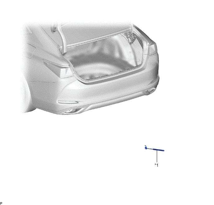
| *1 | LUGGAGE COMPARTMENT DOOR SUPPORT ASSEMBLY | - | - |
READ NEXT:
 Removal
REMOVAL CAUTION / NOTICE / HINT CAUTION: If the luggage compartment door support assembly is removed, the luggage compartment door will slam shut. Make sure to support the luggage compartment door by
Installation
INSTALLATION CAUTION / NOTICE / HINT CAUTION: After installing the luggage compartment door support assembly, use your hand to open and close the luggage door. Make sure the luggage door can open and
Disposal
DISPOSAL PROCEDURE 1. DISPOSE OF LUGGAGE COMPARTMENT DOOR SUPPORT ASSEMBLY (a) Secure the luggage compartment door support assembly horizontally in a vise with the piston rod pulled out.
SEE MORE:
Operation Check
OPERATION CHECK CHECK TIRE PRESSURE WARNING SYSTEM FUNCTION (a) Using the Data List, check that the current tire pressure is normal. Click here (1) Slowly reduce the tire pressure of the front or rear tires and check that the tire pressure on the Data List changes. (2) Further reduce the tire pres
Lost Communication with Airbag System Control Module Circuit Short to Ground (P310711)
DESCRIPTION The hybrid vehicle control ECU detects a problem in the collision signal line from the airbag ECU assembly and alerts the driver. DTC No. Detection Item DTC Detection Condition Trouble Area MIL Warning Indicate P310711 Lost Communication with Airbag System Control Modu
© 2016-2026 Copyright www.lexguide.net
