Lexus ES: Installation
INSTALLATION
PROCEDURE
1. INSTALL NO. 1 FUEL TANK PROTECTOR SUB-ASSEMBLY
(a) Engage the 2 claws to install the No. 1 fuel tank protector sub-assembly to the fuel tank assembly.
2. INSTALL FUEL TANK MAIN TUBE SUB-ASSEMBLY
(a) Engage the 2 clamps to install the fuel tank main tube sub-assembly to the fuel tank assembly.
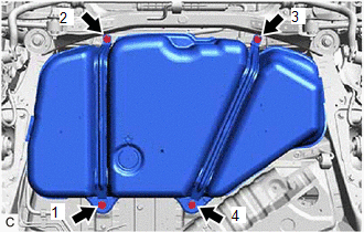
3. INSTALL FUEL TANK ASSEMBLY
CAUTION:
The fuel tank assembly is very heavy. Be sure to follow the procedure described in the repair manual, or the fuel tank assembly may fall off the engine lifter.
.png)
(a) Set the fuel tank assembly on an engine lifter.
NOTICE:
Using height adjustment attachments and plate lift attachments, keep the fuel tank assembly horizontal.
| (b) Using the engine lifter, slowly raise the fuel tank assembly, and then install the fuel tank assembly, No. 1 fuel tank band sub-assembly LH and No. 1 fuel tank band sub-assembly RH with the 4 bolts in the order shown in the illustration. Torque: 45 N·m {459 kgf·cm, 33 ft·lbf} NOTICE:
|
|
4. CONNECT FUEL TANK TO FILLER PIPE HOSE
(a) Connect the fuel tank to filler pipe hose to the fuel tank assembly.
Click here .gif)
5. CONNECT FUEL TANK MAIN TUBE SUB-ASSEMBLY
(a) Connect the fuel tank main tube sub-assembly to the fuel pipe.
Click here
6. INSTALL NO. 1 FUEL TANK PROTECTOR
(a) Install the No. 1 fuel tank protector to the fuel tank assembly with the 3 clips.
7. INSTALL NO. 2 FLOOR UNDER COVER
Click here
8. INSTALL CENTER EXHAUST PIPE ASSEMBLY
Click here
9. INSTALL FUEL SUCTION TUBE WITH PUMP AND GAUGE ASSEMBLY
Click here
10. ADD FUEL
READ NEXT:
 Air Cleaner Filter Element
ComponentsCOMPONENTS ILLUSTRATION *1 AIR CLEANER CAP SUB-ASSEMBLY *2 AIR CLEANER FILTER ELEMENT SUB-ASSEMBLY
SEE MORE:
Torque Converter Clutch Circuit Short to Battery or Open (P074015)
DESCRIPTION Refer to DTC P074011. Click here DTC No. Detection Item DTC Detection Condition Trouble Area MIL Memory Note P074015 Torque Converter Clutch Circuit Short to Battery or Open While the vehicle is being driven so that lock-up is requested, a short to +B or open is
Fuel Rail Pressure Sensor (Low) Signal Stuck in Range (P107A2A,P107A64)
DESCRIPTION Refer to DTC P107A11. Click here DTC No. Detection Item DTC Detection Condition Trouble Area MIL Memory Note P107A2A Fuel Rail Pressure Sensor (Low) Signal Stuck in Range When the target fuel pressure for the low pressure side changes, the change in the No. 2 fue
