Lexus ES: Components
COMPONENTS
ILLUSTRATION
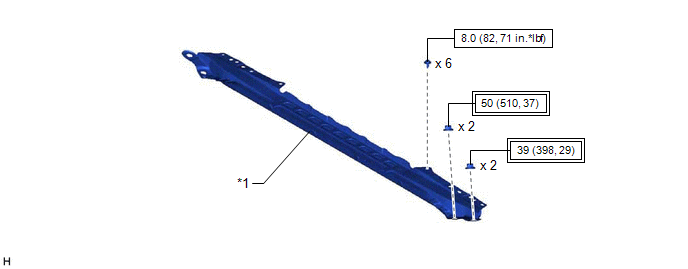
| *1 | FRONT CENTER UPPER SUSPENSION BRACE SUB-ASSEMBLY | - | - |
.png) | Tightening torque for "Major areas involving basic vehicle performance such as moving/turning/stopping": N*m (kgf*cm, ft.*lbf) | .png) | N*m (kgf*cm, ft.*lbf): Specified torque |
ILLUSTRATION
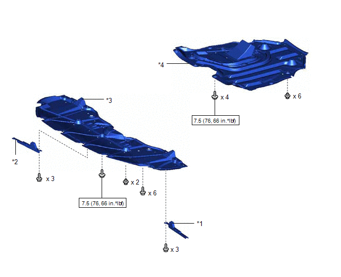
| *1 | FRONT WHEEL OPENING EXTENSION PAD LH | *2 | FRONT WHEEL OPENING EXTENSION PAD RH |
| *3 | NO. 1 ENGINE UNDER COVER | *4 | NO. 2 ENGINE UNDER COVER ASSEMBLY |
| | N*m (kgf*cm, ft.*lbf): Specified torque | - | - |
ILLUSTRATION
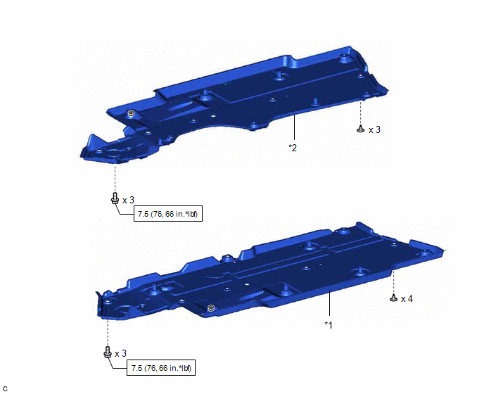
| *1 | FRONT FLOOR COVER LH | *2 | FRONT FLOOR COVER RH |
| | N*m (kgf*cm, ft.*lbf): Specified torque | - | - |
ILLUSTRATION
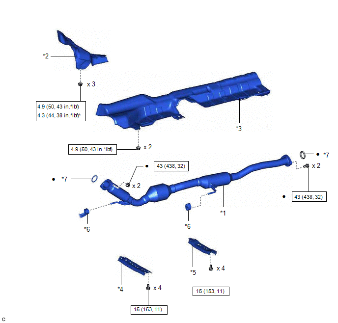
| *1 | FRONT EXHAUST PIPE ASSEMBLY (TWC: Rear Catalyst) | *2 | NO. 1 UPPER FRONT FLOOR HEAT INSULATOR |
| *3 | FRONT LOWER NO. 1 FLOOR HEAT INSULATOR | *4 | CENTER FLOOR CROSSMEMBER BRACE |
| *5 | FRONT CENTER FLOOR BRACE | *6 | EXHAUST PIPE SUPPORT |
| *7 | GASKET | - | - |
| | N*m (kgf*cm, ft.*lbf): Specified torque | * | For use with a union nut wrench |
| ● | Non-reusable part | - | - |
ILLUSTRATION
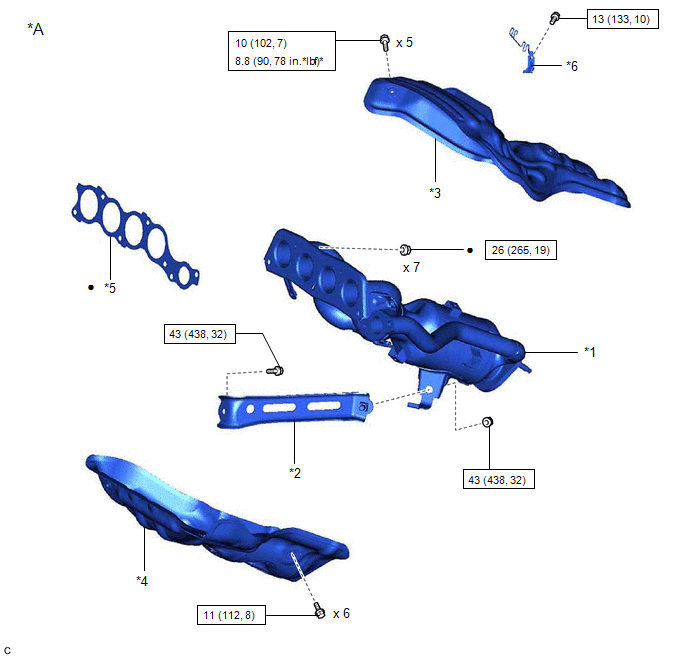
| *A | Type A | - | - |
| *1 | EXHAUST MANIFOLD (TWC: Front Catalyst) | *2 | MANIFOLD STAY |
| *3 | NO. 1 EXHAUST MANIFOLD HEAT INSULATOR | *4 | NO. 2 EXHAUST MANIFOLD HEAT INSULATOR |
| *5 | EXHAUST MANIFOLD TO HEAD GASKET | *6 | WIRE HARNESS CLAMP BRACKET |
| | N*m (kgf*cm, ft.*lbf): Specified torque | * | For use with a union nut wrench |
| ● | Non-reusable part | - | - |
ILLUSTRATION
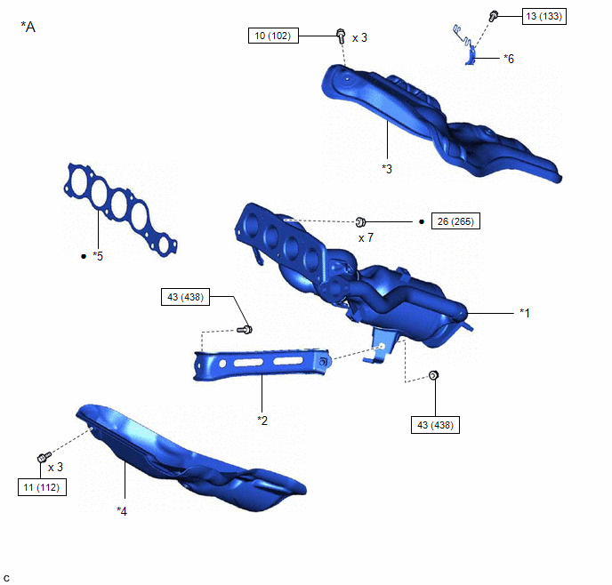
| *A | Type B | - | - |
| *1 | EXHAUST MANIFOLD (TWC: Front Catalyst) | *2 | MANIFOLD STAY |
| *3 | NO. 1 EXHAUST MANIFOLD HEAT INSULATOR | *4 | NO. 2 EXHAUST MANIFOLD HEAT INSULATOR |
| *5 | EXHAUST MANIFOLD TO HEAD GASKET | *6 | WIRE HARNESS CLAMP BRACKET |
| | N*m (kgf*cm, ft.*lbf): Specified torque | - | - |
| ● | Non-reusable part | - | - |
READ NEXT:
 Removal
REMOVAL CAUTION / NOTICE / HINT The necessary procedures (adjustment, calibration, initialization or registration) that must be performed after parts are removed and installed, or replaced during exha
Installation
INSTALLATION PROCEDURE 1. INSTALL NO. 2 EXHAUST MANIFOLD HEAT INSULATOR (a) Type A (1) Install the No. 2 exhaust manifold heat insulator to the exhaust manifold (TWC: Front Catalyst) with the 6 bolts.
SEE MORE:
Diagnostic Trouble Code Chart
DIAGNOSTIC TROUBLE CODE CHART Power Steering System DTC No. Detection Item DTC Detection Condition Warning Indicate Return-to-normal Condition Note Link C1511 Torque Sensor1 Torque sensor malfunction EPS warning light: Comes on Power switch is turned on (IG) again -
How To Proceed With Troubleshooting
CAUTION / NOTICE / HINT HINT:
Use the following procedure to troubleshoot the sliding roof system.
*: Use the Techstream.
PROCEDURE 1. VEHICLE BROUGHT TO WORKSHOP
NEXT 2. CUSTOMER PROBLEM ANALYSIS HINT:
In troubleshooting, confirm that the problem sympto
