Lexus ES: Clearance Warning ECU Power Source Circuit
DESCRIPTION
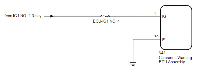
This circuit provides power to operate the clearance warning ECU assembly.
WIRING DIAGRAM
CAUTION / NOTICE / HINT
NOTICE:
Inspect the fuses for circuits related to this system before performing the following procedure.
PROCEDURE
| 1. | CHECK HARNESS AND CONNECTOR (CLEARANCE WARNING ECU ASSEMBLY POWER SOURCE) |
(a) Disconnect the N41 clearance warning ECU assembly connector.
(b) Measure the voltage according to the value(s) in the table below.
Standard Voltage:
| Tester Connection | Condition | Specified Condition |
|---|---|---|
| N41-1 (IG) - Body ground | Engine switch on (IG) | 11 to 14 V |
| N41-1 (IG) - Body ground | Engine switch off | Below 1 V |
| NG |  | REPAIR OR REPLACE HARNESS OR CONNECTOR |
|

| 2. | CHECK HARNESS AND CONNECTOR (CLEARANCE WARNING ECU ASSEMBLY - BODY GROUND) |
(a) Measure the resistance according to the value(s) in the table below.
Standard Resistance:
| Tester Connection | Condition | Specified Condition |
|---|---|---|
| N41-30 (E) - Body ground | Always | Below 1 Ω |
| OK | | PROCEED TO NEXT SUSPECTED AREA SHOWN IN PROBLEM SYMPTOMS TABLE |
.gif)
| NG | | REPAIR OR REPLACE HARNESS OR CONNECTOR |
READ NEXT:
 Customize Parameters
CUSTOMIZE PARAMETERS CUSTOMIZE PARKING SUPPORT ALERT SYSTEM (a) Customizing with the Techstream NOTICE:
When the customer requests a change in a function, first make sure that the function can be c
Data List / Active Test
DATA LIST / ACTIVE TEST DATA LIST NOTICE: In the table below, the values listed under "Normal Condition" are reference values. Do not depend solely on these reference values when deciding whether a pa
Diagnosis System
DIAGNOSIS SYSTEM DESCRIPTION (a) When troubleshooting a vehicle with a diagnosis system, the only difference from the usual troubleshooting procedure is connecting the Techstream to the vehicle and re
SEE MORE:
Customize Parameters
CUSTOMIZE PARAMETERS CUSTOMIZE LIGHTING SYSTEM (EXT) NOTICE:
When the customer requests a change in a function, first make sure that the function can be customized.
Be sure to make a note of the current settings before customizing.
When troubleshooting a function, first make sure that the fun
Components
COMPONENTS ILLUSTRATION *1 COWL SIDE TRIM BOARD LH *2 FRONT DOOR OPENING TRIM COVER LH *3 FRONT DOOR SCUFF PLATE LH *4 INSTRUMENT PANEL FINISH PANEL END LH *5 INSTRUMENT SIDE PANEL LH *6 LOWER INSTRUMENT PANEL *7 LOWER INSTRUMENT PANEL FINISH PANEL SUB-ASSEMBLY
