Lexus ES: Calibration
CALIBRATION
ADJUST PANORAMIC VIEW MONITOR SYSTEM
(a) This panoramic view monitor system can be set from the diagnostic screen of the multi-display assembly.
(b) If the following operations are performed, it is necessary to perform adjustments and checks on the diagnostic screen.
| Part Name | Operation | Adjustment Item | Proceed to |
|---|---|---|---|
| Steering sensor |
| Steering angle neutral point (Initialize panoramic view monitor system) | |
| Procedure 9 | |||
| Parking assist ECU | Replacement | Parking assist ECU initialization | Procedure 2 |
| Procedure 7 | |||
| Procedure 8 | |||
| Adjust steering angle | Procedure 9 | ||
| Suspension, tires, etc. | The vehicle height changes because of suspension or tire replacement | Parking assist ECU initialization | Procedure 2 |
| Procedure 7 | |||
| Procedure 8 | |||
| Adjust steering angle | Procedure 9 | ||
| Rear television camera assembly optical axis (Back camera position setting) | Procedure 10 | ||
| Rear television camera assembly |
| Rear television camera view adjustment | Procedure 2 |
| Procedure 4 | |||
| Procedure 8 | |||
| Rear television camera assembly optical axis (Back camera position setting) | Procedure 10 | ||
|
| Front television camera view adjustment | Procedure 2 |
| Procedure 3 | |||
| Procedure 8 | |||
| Side television camera assembly LH Outer rear view mirror assembly LH |
| Side television camera view adjustment | Procedure 2 |
| Procedure 5 | |||
| Procedure 8 | |||
| Side television camera assembly RH Outer rear view mirror assembly RH |
| Side television camera view adjustment | Procedure 2 |
| Procedure 6 | |||
| Procedure 8 | |||
| Replacement or removal and installation of 2 or more parts | Television camera view adjustment | Procedure 2 |
| Procedure 7 | |||
| Procedure 8 | |||
| Rear television camera assembly optical axis (Back camera position setting)* | Procedure 10 |
- *: Applies only for when removing and installing or replacing the rear television camera assembly.
HINT:
The adjustment values stored while performing panoramic view monitor system calibration are stored in the parking assist ECU.
Procedure 1: PRE-WORK CHECKS
(a) Preliminary checks
NOTICE:
- Provide shadow to prevent back-up light from hitting the camera.
- Use string that does not stretch.
- Apply pieces of adhesive tape to serve as check markers. When placing the markers, make them 100 mm (3.94 in.) wide.
(1) Perform the work at a wide, level location (4000 to 7300 mm [13.12 to 23.94 ft.]).
(2) Park the vehicle on a flat surface with the steering wheel centered.
NOTICE:
Before stopping the vehicle, move the vehicle backward and forward to ensure that both the steering wheel and the tires point straight ahead.
(3) Adjust the tire pressure to the specified value(s).
(4) Remove all luggage from the vehicle before starting work.
(b) Marker locations
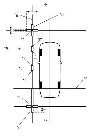
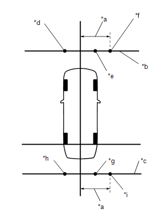
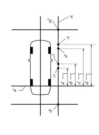
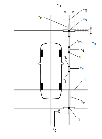
(1) Secure the string to the locations required to make the checks and set markers as shown in the illustration.
-
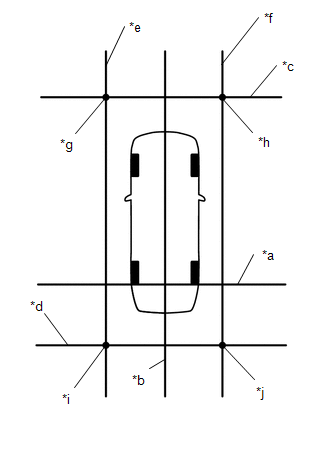
Front camera adjustment only
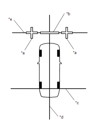
*a
Cross Check Marker
*b
Check Marker
*c
String 1
*d
String 2
*e
String 3
-
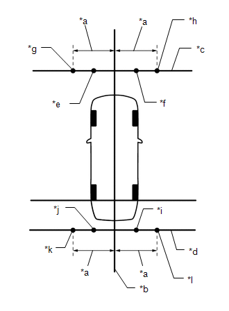
Rear camera adjustment only
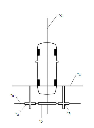
*a
Cross Check Marker
*b
Check Marker
*c
String 1
*d
String 2
*e
String 4
-
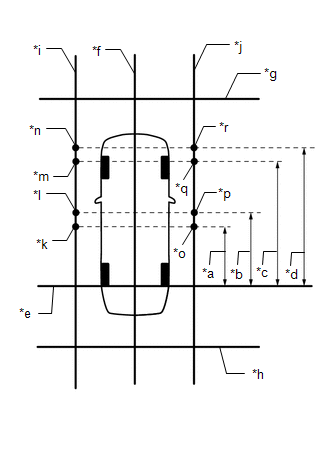
Left camera adjustment only
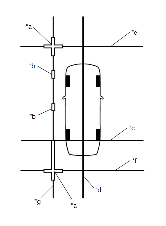
*a
Cross Check Marker
*b
Check Marker
*c
String 1
*d
String 2
*e
String 3
*f
String 4
*g
String 5
-
Right camera adjustment only
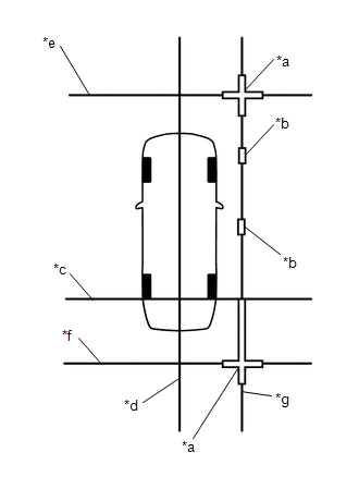
*a
Cross Check Marker
*b
Check Marker
*c
String 1
*d
String 2
*e
String 3
*f
String 4
*g
String 6
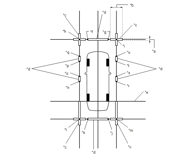
-
Adjustment of 4 cameras
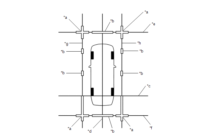
*a
Cross Check Marker
*b
Check Marker
*c
String 1
*d
String 2
*e
String 3
*f
String 4
*g
String 5
*h
String 6
(c) Marker positions
(1) Set the check markers at the positions shown in the illustration.
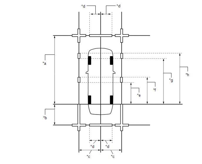
| *a | 4800 mm (15.7 ft.) | *b | 1500 mm (4.92 ft.) |
| *c | 1400 mm (4.59 ft.) | *d | 693 mm (2.27 ft.) |
| *e | 1400 mm (4.59 ft.) | *f | 1600 mm (5.25 ft.) |
| *g | 3100 mm (10.2 ft.) | *h | 3300 mm (10.8 ft.) |
PROCEDURE 2: SET DATUM POINTS
(a) Extend the datum line (string 1).
(1) Hang a weight with a pointed tip and accurately mark the center position on the road surface. (Mark A)
NOTICE:
Make sure that the weight hangs straight down from the string.
| *a | Mark A |
| *b | Weight |
(2) Repeat the procedure to mark the right side. (Mark B)
(3) Secure string 1 so that it passes through marks A and B on the left and right sides.
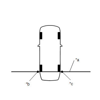
| *a | String 1 |
| *b | Mark A |
| *c | Mark B |
NOTICE:
When securing the string, check that there is no slack and the string is not twisted.
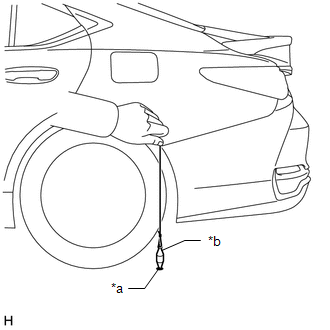
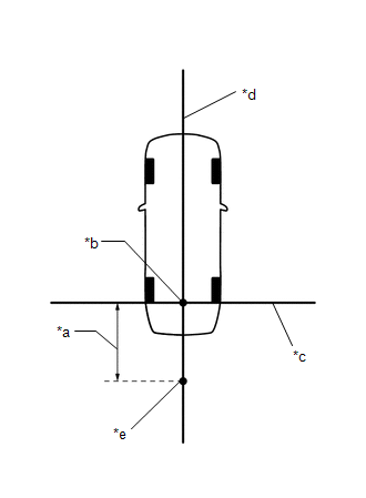
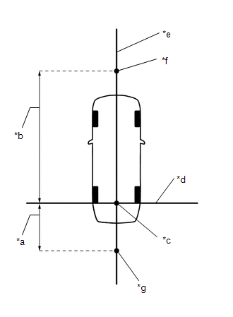
(b) Extend the vehicle center line (string 2).
(1) Hang a weight with a pointed tip so that it passes through the center of the front television camera assembly and accurately mark the center position on the road surface. (Mark C)
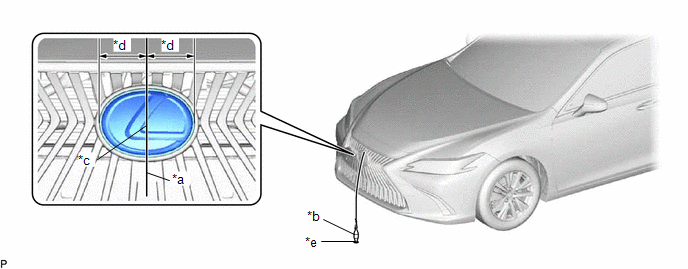
| *a | String | *b | Weight |
| *c | Center | *d | Bilateral Symmetry |
| *e | Mark C | - | - |
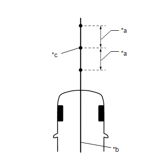
(2) Hang a weight with a pointed tip from the center of the rear emblem and accurately mark the center position on the road surface. (Mark D)
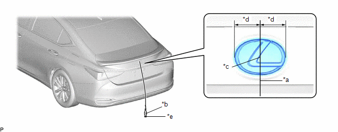
| *a | String | *b | Weight |
| *c | Center | *d | Bilateral Symmetry |
| *e | Mark D | - | - |
(3) Secure string 2 so that it passes through marks C and D at the front and rear of the vehicle.
NOTICE:
When securing string 2, check that there is no slack and the string is not twisted.
HINT:
Set the point where strings 1 and 2 intersect as the datum point.
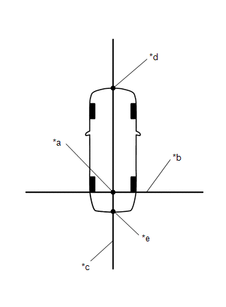
| *a | Datum Point |
| *b | String 1 |
| *c | String 2 |
| *d | Mark C |
| *e | Mark D |
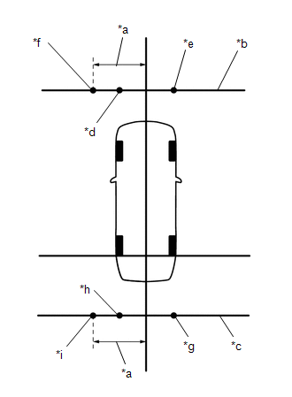
PROCEDURE 3: SET MARKERS (when checking front)
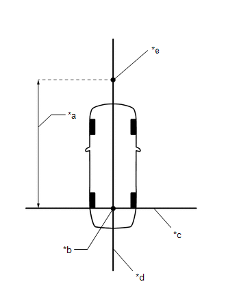
| *a | 4800 mm (15.7 ft.) |
| *b | Datum Point |
| *c | String 1 |
| *d | String 2 |
| *e | Mark E |
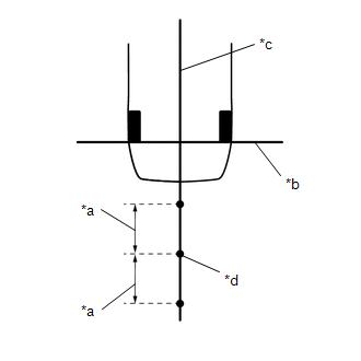
(a) In front of the vehicle, extend string 3 perpendicular to the vehicle center line (string 2) and place a marker.
(1) Mark the position on string 2 in front of the vehicle, 4800 mm (15.7 ft.) from the datum point. (Mark E)
(2) Secure the ends of 2 strings (800 mm [2.62 ft.] long) at 2 positions 400 mm (1.31 ft.) from mark E as shown in the illustration.
| *a | 400 mm (1.31 ft.) |
| *b | String 2 |
| *c | Mark E |
(3) Move the free ends of the 2 strings and mark the point where the ends meet. (Marks F and G)
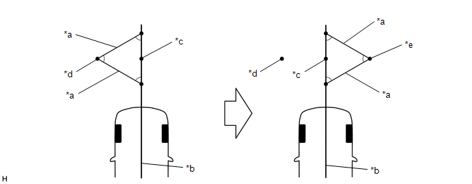
| *a | 800 mm (2.62 ft.) String | *b | String 2 |
| *c | Mark E | *d | Mark F |
| *e | Mark G | - | - |
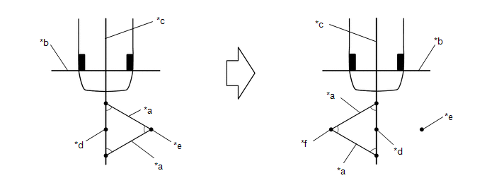
(4) Secure string 3 so that it passes through marks F and G as shown in the illustration.
NOTICE:
When securing the string, check that there is no slack and the string is not twisted.
| *a | 1400 mm (4.59 ft.) |
| *b | String 1 |
| *c | String 2 |
| *d | String 3 |
| *e | Mark F |
| *f | Mark G |
| *g | Mark H |
| *h | Mark I |
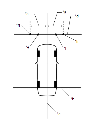
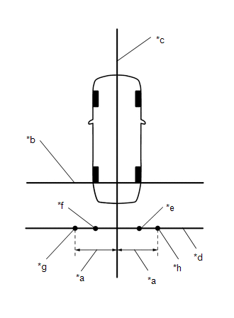
(5) Mark positions on string 3, 1400 mm (4.59 ft.) to the left and right of the vehicle center line (string 2). (Marks H and I).
(6) Place and secure the cross check markers, centered on marks H and I.
| *a | 800 mm (2.62 ft.) |
| *b | 100 mm (0.33 ft.) |
| *c | Cross Check Marker |
| *d | Check Marker |
| *e | Mark F |
| *f | Mark G |
| *g | Mark H |
| *h | Mark I |
NOTICE:
- Align the cross check markers perpendicular to the string.
- Make each arm of the cross check markers 800 mm (2.62 ft.) long and 100 mm (0.33 ft.) wide.
(7) Place the check marker between marks F and G.
(8) Perform camera view adjustment (calibration) (procedure 8).
PROCEDURE 4: SET MARKERS (When checking rear)
(a) To the rear of the vehicle, extend string 4 perpendicular to the vehicle center line (string 2) and place a check marker.
(1) Mark a position on string 2 to the rear of the vehicle, 1500 mm (4.92 ft.) from the datum point. (Mark J)
| *a | 1500 mm (4.92 ft.) |
| *b | Datum Point |
| *c | String 1 |
| *d | String 2 |
| *e | Mark J |
(2) Secure the ends of 2 strings (800 mm [2.62 ft.]) at 2 positions 400 mm (1.31 ft.) from mark J as shown in the illustration.
| *a | 400 mm (1.31 ft.) |
| *b | String 1 |
| *c | String 2 |
| *d | Mark J |
(3) Move the free ends of the 2 strings and mark the point where the ends meet. (Marks K and L)
| *a | 800 mm (2.62 ft.) String | *b | String 1 |
| *c | String 2 | *d | Mark J |
| *e | Mark K | *f | Mark L |
(4) Secure string 4 so that it passes through marks K and L as shown in the illustration.
| *a | 1400 mm (4.59 ft.) |
| *b | String 1 |
| *c | String 2 |
| *d | String 4 |
| *e | Mark K |
| *f | Mark L |
| *g | Mark M |
| *h | Mark N |
NOTICE:
When securing the string, check that there is no slack and the string is not twisted.
(5) Mark positions on string 4, 1400 mm (4.59 ft.) to the left and right of the vehicle center line (string 2). (Marks M and N)
(6) Place and secure the cross check markers, centered on marks M and N.
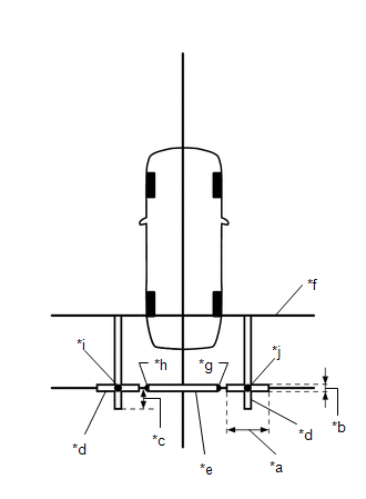
| *a | 800 mm (2.62 ft.) |
| *b | 100 mm (0.33 ft.) |
| *c | 400 mm (1.31 ft.) |
| *d | Cross Check Marker |
| *e | Check Marker |
| *f | String 1 |
| *g | Mark K |
| *h | Mark L |
| *i | Mark M |
| *j | Mark N |
NOTICE:
- Align the cross check markers perpendicular to the string.
- Make each arm of the cross check markers 800 mm (2.62 ft.) long and 100 mm (0.33 ft.) wide.
- Extend the rear cross check markers to string 1.
(7) Place the check marker between marks K and L.
(8) Perform camera view adjustment (calibration) (procedure 8).
PROCEDURE 5: SET MARKERS (When checking left side)
(a) To the left side of the vehicle, extend string 5 parallel to the vehicle center line (string 2) and place a check marker.
(1) Mark the position on string 2 in front of the vehicle, 4800 mm (15.7 ft.) from the datum point. (Mark E)
| *a | 1500 mm (4.92 ft.) |
| *b | 4800 mm (15.7 ft.) |
| *c | Datum Point |
| *d | String 1 |
| *e | String 2 |
| *f | Mark E |
| *g | Mark J |
(2) Mark the position on string 2 to the rear of the vehicle, 1500 mm (4.92 ft.) from the datum point. (Mark J)
(3) Secure the ends of 2 strings (800 mm [2.62 ft.] long) at 2 positions 400 mm (1.31 ft.) from mark E as shown in the illustration.
| *a | 400 mm (1.31 ft.) |
| *b | String 2 |
| *c | Mark E |
(4) Move the free ends of the 2 strings and mark the point where the ends meet. (Marks F and G)
| *a | 800 mm (2.62 ft.) String | *b | String 2 |
| *c | Mark E | *d | Mark F |
| *e | Mark G | - | - |
(5) Secure the ends of 2 strings (800 mm [2.62 ft.]) at 2 positions 400 mm (1.31 ft.) from mark J as shown in the illustration.
| *a | 400 mm (1.31 ft.) |
| *b | String 1 |
| *c | String 2 |
| *d | Mark J |
(6) Move the free ends of the 2 strings and mark the point where the ends meet. (Marks K and L)
| *a | 800 mm (2.62 ft.) String | *b | String 1 |
| *c | String 2 | *d | Mark J |
| *e | Mark K | *f | Mark L |
(7) Secure strings 3 and 4 so that they pass through marks F and G, marks K and L as shown in the illustration.
NOTICE:
When securing the string, check that there is no slack and the string is not twisted.
| *a | 1400 mm (4.59 ft.) |
| *b | String 3 |
| *c | String 4 |
| *d | Mark F |
| *e | Mark G |
| *f | Mark H |
| *g | Mark K |
| *h | Mark L |
| *i | Mark M |
(8) Mark strings 3 and 4, 1400 mm (4.59 ft.) to the left of the vehicle center line (string 2). (Marks H and M)
(9) Secure string 5 so that it passes through marks H and M as shown in the illustration.
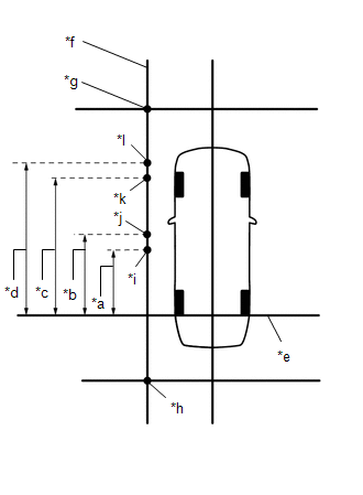
| *a | 1400 mm (4.59 ft.) |
| *b | 1600 mm (5.25 ft.) |
| *c | 3100 mm (10.2 ft.) |
| *d | 3300 mm (10.8 ft.) |
| *e | String 1 |
| *f | String 5 |
| *g | Mark H |
| *h | Mark M |
| *i | Mark O |
| *j | Mark P |
| *k | Mark Q |
| *l | Mark R |
NOTICE:
When securing the string, check that there is no slack and the string is not twisted.
(10) Make marks on string 5 that are 1400 mm (4.59 ft.), 1600 mm (5.25 ft.), 3100 mm (10.2 ft.) and 3300 mm (10.8 ft.) from the datum line (string 1) as shown in the illustration. (Marks O, P, Q and R)
(11) Place and secure the cross check markers, centered on marks H and M.
| *a | 100 mm (0.33 ft.) |
| *b | 800 mm (2.62 ft.) |
| *c | 400 mm (1.31 ft.) |
| *d | Cross Check Marker |
| *e | Check Marker |
| *f | String 1 |
| *g | String 5 |
| *h | Mark H |
| *i | Mark M |
| *j | Mark O |
| *k | Mark P |
| *l | Mark Q |
| *m | Mark R |
NOTICE:
- Align the cross check markers perpendicular to the string.
- Make each arm of the cross check markers 800 mm (2.62 ft.) long and 100 mm (0.33 ft.) wide.
- Extend the rear cross check markers to string 1.
(12) Place check markers between marks O and P, and marks Q and R.
(13) Perform camera view adjustment (calibration) (procedure 8).
PROCEDURE 6: SET MARKERS (When checking right side)
(a) At the right side of the vehicle, extend string 6 parallel to the vehicle and place a marker.
(1) Mark the position on string 2 in front of the vehicle, 4800 mm (15.7 ft.) from the datum point. (Mark E)
| *a | 1500 mm (4.92 ft.) |
| *b | 4800 mm (15.7 ft.) |
| *c | Datum Point |
| *d | String 1 |
| *e | String 2 |
| *f | Mark E |
| *g | Mark J |
(2) Mark the position on string 2 to the rear of the vehicle, 1500 mm (4.92 ft.) from the datum point. (Mark J)
(3) Secure the ends of 2 strings (800 mm [2.62 ft.] long) at 2 positions 400 mm (1.31 ft.) from mark E as shown in the illustration.
| *a | 400 mm (1.31 ft.) |
| *b | String 2 |
| *c | Mark E |
(4) Move the free ends of the 2 strings and mark the point where the ends meet. (Marks F and G)
| *a | 800 mm (2.62 ft.) String | *b | String 2 |
| *c | Mark E | *d | Mark F |
| *e | Mark G | - | - |
(5) Secure the ends of 2 strings (800 mm [2.62 ft.]) at 2 positions 400 mm (1.31 ft.) from mark J as shown in the illustration.
| *a | 400 mm (1.31 ft.) |
| *b | String 1 |
| *c | String 2 |
| *d | Mark J |
(6) Move the free ends of the 2 strings and mark the point where the ends meet. (Marks K and L)
| *a | 800 mm (2.62 ft.) String | *b | String 1 |
| *c | String 2 | *d | Mark J |
| *e | Mark K | *f | Mark L |
(7) Secure strings 3 and 4 so that they pass through marks F and G and marks K and L as shown in the illustration.
NOTICE:
When securing the string, check that there is no slack and the string is not twisted.
| *a | 1400 mm (4.59 ft.) |
| *b | String 3 |
| *c | String 4 |
| *d | Mark F |
| *e | Mark G |
| *f | Mark I |
| *g | Mark K |
| *h | Mark L |
| *i | Mark N |
(8) Mark strings 3 and 4, 1400 mm (4.59 ft.) to the right of the vehicle center line (string 2). (Marks I and N)
(9) Secure string 6 so that it passes through marks I and N as shown in the illustration.
| *a | 1400 mm (4.59 ft.) |
| *b | 1600 mm (5.25 ft.) |
| *c | 3100 mm (10.2 ft.) |
| *d | 3300 mm (10.8 ft.) |
| *e | String 1 |
| *f | String 6 |
| *g | Mark I |
| *h | Mark N |
| *i | Mark S |
| *j | Mark T |
| *k | Mark U |
| *l | Mark V |
NOTICE:
When securing the string, check that there is no slack and the string is not twisted.
(10) Make marks on string 6 that are 1400 mm (4.59 ft.), 1600 mm (5.25 ft.), 3100 mm (10.2 ft.) and 3300 mm (10.8 ft.) from the datum line (string 1) as shown in the illustration. (Marks S, T, U and V)
(11) Place and secure the cross check markers, centered on marks I and N.
| *a | 100 mm (0.33 ft.) |
| *b | 800 mm (2.62 ft.) |
| *c | 400 mm (1.31 ft.) |
| *d | Cross Check Marker |
| *e | Check Marker |
| *f | String 1 |
| *g | String 6 |
| *h | Mark I |
| *i | Mark N |
| *j | Mark S |
| *k | Mark T |
| *l | Mark U |
| *m | Mark V |
NOTICE:
- Align the cross check markers perpendicular to the string.
- Make each arm of the cross check markers 800 mm (2.62 ft.) long and 100 mm (0.33 ft.) wide.
- Extend the rear cross check markers to string 1.
(12) Place check markers between marks S and T, and marks U and V.
(13) Perform camera view adjustment (calibration) (procedure 8).
PROCEDURE 7: SET MARKERS (When checking all cameras)
(a) Set markers in every direction from the vehicle.
| *a | 1500 mm (4.92 ft.) |
| *b | 4800 mm (15.7 ft.) |
| *c | Datum Point |
| *d | String 1 |
| *e | String 2 |
| *f | Mark E |
| *g | Mark J |
(1) Mark the position on string 2 in front of the vehicle, 4800 mm (15.7 ft.) from the datum point. (Mark E)
(2) Mark the position on string 2 to the rear of the vehicle, 1500 mm (4.92 ft.) from the datum point. (Mark J)
| *a | 400 mm (1.31 ft.) |
| *b | String 2 |
| *c | Mark E |
(3) Secure the ends of 2 strings (800 mm [2.62 ft.] long) at 2 positions 400 mm (1.31 ft.) from mark E as shown in the illustration.
(4) Move the free ends of the 2 strings and mark the point where the ends meet. (Marks F and G)
| *a | 800 mm (2.62 ft.) String | *b | String 2 |
| *c | Mark E | *d | Mark F |
| *e | Mark G | - | - |
| *a | 400 mm (1.31 ft.) |
| *b | String 1 |
| *c | String 2 |
| *d | Mark J |
(5) Secure the ends of 2 strings (800 mm [2.62 ft.]) at 2 positions 400 mm (1.31 ft.) from mark J as shown in the illustration.
(6) Move the free ends of the 2 strings and mark the point where the ends meet. (Marks K and L)
| *a | 800 mm (2.62 ft.) String | *b | String 1 |
| *c | String 2 | *d | Mark J |
| *e | Mark K | *f | Mark L |
(7) Secure strings 3 and 4 so that they pass through marks F, G, K and L as shown in the illustration.
| *a | 1400 mm (4.59 ft.) |
| *b | String 2 |
| *c | String 3 |
| *d | String 4 |
| *e | Mark F |
| *f | Mark G |
| *g | Mark H |
| *h | Mark I |
| *i | Mark K |
| *j | Mark L |
| *k | Mark M |
| *l | Mark N |
NOTICE:
When securing the string, check that there is no slack and the string is not twisted.
(8) Mark string 3, 1400 mm (4.59 ft.) to the left and right of the vehicle center line (string 2). (Marks H and I)
(9) Mark string 4, 1400 mm (4.59 ft.) to the left and right of the vehicle center line (string 2). (Marks M and N)
(10) Secure strings 5 and 6 so that they pass through marks H, M, I and N as shown in the illustration.
NOTICE:
When securing the string, check that there is no slack and the string is not twisted.
| *a | String 1 |
| *b | String 2 |
| *c | String 3 |
| *d | String 4 |
| *e | String 5 |
| *f | String 6 |
| *g | Mark H |
| *h | Mark I |
| *i | Mark M |
| *j | Mark N |
| *a | 1400 mm (4.59 ft.) |
| *b | 1600 mm (5.25 ft.) |
| *c | 3100 mm (10.2 ft.) |
| *d | 3300 mm (10.8 ft.) |
| *e | String 1 |
| *f | String 2 |
| *g | String 3 |
| *h | String 4 |
| *i | String 5 |
| *j | String 6 |
| *k | Mark O |
| *l | Mark P |
| *m | Mark Q |
| *n | Mark R |
| *o | Mark S |
| *p | Mark T |
| *q | Mark U |
| *r | Mark V |
(11) Make marks on string 5 that are 1400 mm (4.59 ft.), 1600 mm (5.25 ft.), 3100 mm (10.2 ft.) and 3300 mm (10.8 ft.) from the datum line (string 1) as shown in the illustration. (Marks O, P, Q and R)
(12) Make marks on string 6 that are 1400 mm (4.59 ft.), 1600 mm (5.25 ft.), 3100 mm (10.2 ft.) and 3300 mm (10.8 ft.) from the datum line (string 1) as shown in the illustration. (Marks S, T, U and V)
(13) Place and secure the cross check markers, centered on marks H, I, M and N.
NOTICE:
- Align the cross check markers perpendicular to the string.
- Make each arm of the cross check markers 800 mm (2.62 ft.) long and 100 mm (0.33 ft.) wide.
- Extend the rear cross check markers to string 1.
| *a | 100 mm (0.33 ft.) | *b | 800 mm (2.62 ft.) |
| *c | Cross Check Marker | *d | Check Marker |
| *e | String 1 | *f | Mark F |
| *g | Mark G | *h | Mark H |
| *i | Mark I | *j | Mark K |
| *k | Mark L | *l | Mark M |
| *m | Mark N | *n | Mark O |
| *o | Mark P | *p | Mark Q |
| *q | Mark R | *r | Mark S |
| *s | Mark T | *t | Mark U |
| *u | Mark V | - | - |
(14) Place check markers between marks F and G, marks K and L, marks O and P, marks Q and R, marks S and T, and marks U and V.
(15) Perform camera view adjustment (calibration) (procedure 8).
PROCEDURE 8: CAMERA VIEW ADJUSTMENT (CALIBRATION)
(a) Start diagnostic mode.
-
w/ Navigation system: Click here
.gif)
-
w/o Navigation system: Click here
NOTICE:
The following must be carried out with the engine running. Apply the parking brake, depress the brake pedal, check that the shift lever is in P, and ensure that the vehicle is not moving.
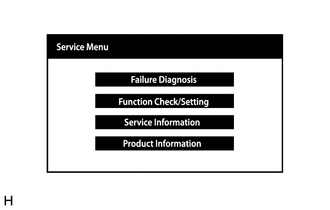
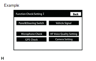
(b) Select "Function Check/Setting" from the "Service Menu" screen.
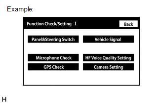
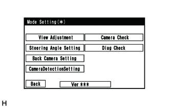
(c) Select "Camera Setting" on the "Function Check/Setting I" screen to display the Mode Setting screen.
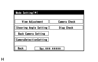
(d) Select "View Adjustment" on the Mode Setting screen to display the adjustment screen.
HINT:
To select a grayed out item, select and hold the item for 2 seconds or more.
(e) After checking the screen, press the "NEXT" button on the "Signal Check" screen.
.png)
HINT:
- When "CHK" (red) is displayed, perform the inspections.
- If performing the adjustment after proceeding to the next screen, check that all items display "OK" (blue) before selecting "Next".
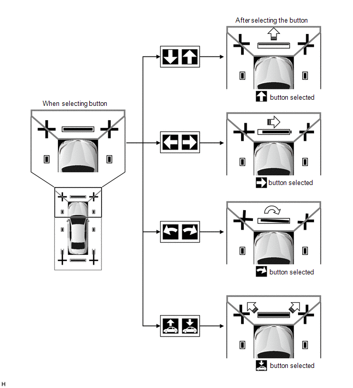
(f) Perform the view adjustment.
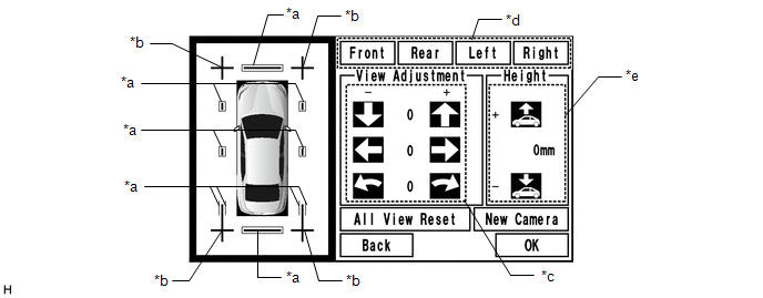
| *a | Red Line | *b | Cross Check Marker |
| *c | Adjustment Button | *d | Camera Select Button |
| *e | Height Control Button | - | - |
NOTICE:
If replacing a camera, select the repaired camera and press "New Camera".
(1) Check that the cross check markers displayed on the adjustment screen appear connected.
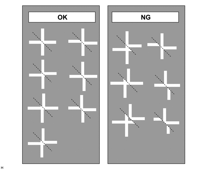
NOTICE:
- Before checking the adjustment screen, ensure that the check markers have been placed correctly.
-
If a cross check marker appears displaced on the adjustment screen, use the camera select buttons to select the corresponding camera, and then use the adjustment buttons or vehicle height adjustment buttons to adjust the screen.
HINT:
If adjustment is needed, select "All View Reset" button and reset all adjustment values.
(2) Check the check marker is in the adjustment screen.
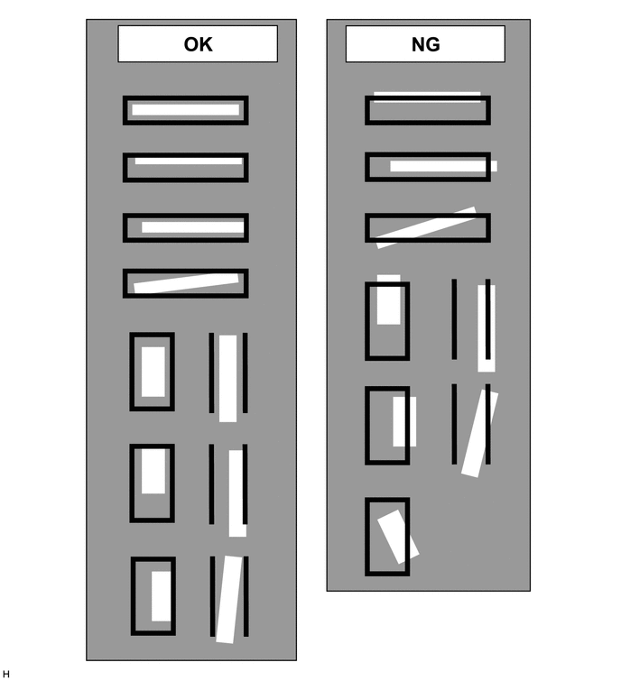
NOTICE:
- Before checking the adjustment screen, ensure that the check markers have been placed correctly.
-
If a check marker appears displaced on the adjustment screen, use the camera select buttons to select the corresponding camera, and then use the adjustment buttons or vehicle height adjustment buttons to adjust the screen.
HINT:
If performing adjustment again, select "All View Reset" to initialize the adjustment status.
(g) When all adjustments are completed, press "OK".
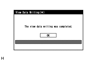
(h) If data writing ends normally, "The view data writing was completed." is displayed.
(i) Press "OK".
(j) Finish diagnostic mode.
-
w/ Navigation system: Click here
-
w/o Navigation system: Click here
PROCEDURE 9: STEERING ANGLE SETTING
(a) Preparation for adjustment
(1) Park the vehicle with the steering wheel centered.
HINT:
Before parking the vehicle, be sure to move the vehicle forward and in reverse to check that the tires are facing straight ahead with the steering wheel centered.
(2) Adjust the tire pressure to the specified value(s).
(b) Start diagnostic mode.
-
w/ Navigation system: Click here
-
w/o Navigation system: Click here
NOTICE:
The following must be carried out with the engine running. Apply the parking brake, depress the brake pedal, check that the shift lever is in P, and ensure that the vehicle is not moving.
(c) Select "Function Check/Setting" on the "Service Menu" screen.
(d) Select "Camera Setting" on the "Function Check/Setting I" screen.

(e) Select "Steering Angle Setting" on the Mode Setting screen to display the Signal Check screen.
HINT:
To select a grayed out item, select and hold the item for 2 seconds or more.
(f) Select "Next" on the Signal Check screen to display the Steering Angle Setting screen.
NOTICE:
- If "CHK" (red) is displayed for an item on the Signal Check screen, selecting "Next" will not change to the Steering Angle Setting screen.
- Check the Signal Check screen when "CHK" (red) is displayed for an item on the Signal Check screen.
(g) Adjust the steering angle
(1) Check that the steering wheel is centered (approximately +/- 5 degrees or less) and then select "Steering Center Memorize".
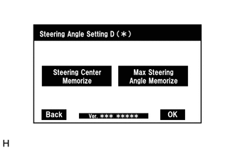
(2) Turn the steering wheel fully to the left and fully to the right, and then press "Max Steering Angle Memorize". (Turning right and then left is OK)
(3) When "Max Steering Angle Memorize" is selected, the system beeps, the steering angle setting values (steering neutral point and maximum steering angle) are stored, and the Mode Setting screen is displayed again.
HINT:
- A beep will sound to confirm that the adjustment values have been stored.
- If all signals are input normally, the Mode Setting screen is displayed automatically after the maximum steering angle is stored.
- If steering angle setting is incomplete, "OK" cannot be selected.
- Even if no DTC is detected, a steering sensor malfunction may disable the use of "Max Steering Angle Memorize".
-
If selecting "Max Steering Angle Memorize" does not cause the adjustment value to be stored after adjusting the steering angle, replace the steering sensor.
Click here
(h) Finish diagnostic mode.
-
w/ Navigation system: Click here
-
w/o Navigation system: Click here
(i) Check steering angle adjustment.
HINT:
If the steering angle has been adjusted, check the steering angle adjustment on the panoramic view monitor screen after finishing diagnosis mode.
(j) Check on the parking assist monitor screen that the estimated course line moves until the steering wheel is fully turned to either the left or right.
HINT:
If the estimated course line stops moving before the steering wheel is fully turned to either the left or right, the steering angle adjustment values have not been stored correctly. In this case, perform "Steering Center Memorize" and "Max Steering Angle Memorize" again.
PROCEDURE 10: BACK CAMERA POSITION SETTING
HINT:
-
Be sure to check for DTCs before performing this procedure.
Click here
- Illustrations may differ from the actual vehicle screen depending on the device settings and options. Therefore, some detailed areas may not be shown exactly the same as on the actual vehicle screen.
(a) Preparation for adjustment
(1) Park the vehicle with the steering wheel centered.
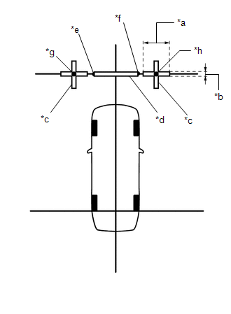
(2) Set a target bar behind the vehicle for optical axis adjustment of the rear television camera assembly (back camera position setting).
HINT:
Create a target bar for adjustment only when adjusting the optical axis of the rear television camera assembly.
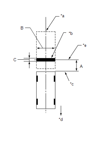
| *a | Vehicle Center |
| *b | Target Bar for Back Camera Position Setting |
| *c | Vehicle End |
| *d | Front |
| *e | Target Bar Center Axis |
Dimension:
| Area | Specification |
|---|---|
| A | 1000 mm (3.28 ft.) |
| B | 1995 to 2005 mm (6.544 to 6.576 ft.) |
| C | 100 mm (3.94 in.) |
HINT:
- Set a piece of tape on the ground as the target bar for adjustment. Its width and length should be 100 mm (3.94 in.) and 1995 to 2005 mm (6.544 to 6.576 ft.), respectively.
- Use a high contrast tape color (black tape on a light surface, white tape on a dark surface, etc.).
- Do not use tape which has a pattern such as a stripe.
- Make sure that there are no lines other than the target bar in the target area.
- Before parking the vehicle, be sure to move the vehicle forward and in reverse to check that the tires are facing straight ahead with the steering wheel centered.
- Check that the luggage compartment door is fully closed.
(b) Start diagnostic mode.
-
w/ Navigation system: Click here
-
w/o Navigation system: Click here
NOTICE:
The following must be carried out with the engine started. Apply the parking brake, depress the brake pedal, check that the shift lever is in P, and ensure that the vehicle is not moving.
(1) Select "Function Check/Setting" on the "Service Menu" screen.
(2) Select "Camera Setting" on the "Function Check/Setting I" screen.
(3) Select "Back Camera Setting" on the "Mode Setting" screen.
HINT:
To select a grayed out item, select and hold the item for 2 seconds or more.
(4) Select "Next" on the "Signal Check" screen.
HINT:
- When "CHK" (red) is displayed for any items on the "Signal Check" screen, selecting "Next" will not change the screen to the "Back Camera Position Setting D (*)" screen.
-
When "CHK" (red) is displayed for any items on the "Signal Check" screen, perform inspections using the "Signal Check" screen.
Click here
(c) Back Camera Position Setting (Both Ends of Target Bar)
HINT:
- When the luggage compartment door is open, the "You can not calibrate the camera when the door is open. Please close the door." message will be displayed and camera position setting will not be possible.
-
If the "You can not calibrate the camera when the door is open. Please close the door." message is displayed even when the luggage compartment door is closed, perform inspections according to Problem Symptoms Table (When adjusting the camera optical axis, "You can not calibrate the camera when the door is open. Please close the door." is displayed even after the luggage compartment door has been closed).
Click here
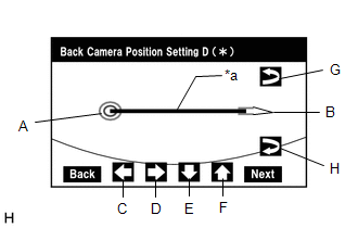
| *a | Target Bar for Back Camera Position Setting |
(1) Perform vertical and horizontal position adjustment.
- Move the circle (A) left, right, up and down by selecting the buttons (C), (D), (E) and (F) so that the left end of Target Bar for Back Camera Position Setting is positioned within the center of the circle (A) (center of the inner red circle).
(2) Perform roll angle adjustment.
- Rotate the bar (B) by selecting the buttons (G) or (H) so that the bar (B) becomes parallel to Target Bar for Back Camera Position Setting.
(3) Select "Next" on the "Back Camera Position Setting D (*)" screen.
(d) Back Camera Position Setting (Upper Left Corner of Target Bar)
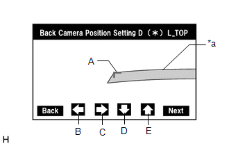
| *a | Target Bar for Back Camera Position Setting |
HINT:
- When the luggage compartment door is open, the "You can not calibrate the camera when the door is open. Please close the door." message will be displayed and camera position setting will not be possible.
-
If the "You can not calibrate the camera when the door is open. Please close the door." message is displayed even when the luggage compartment door is closed, perform inspections according to Problem Symptoms Table (When adjusting the camera optical axis, "You can not calibrate the camera when the door is open. Please close the door." is displayed even after the luggage compartment door has been closed).
Click here
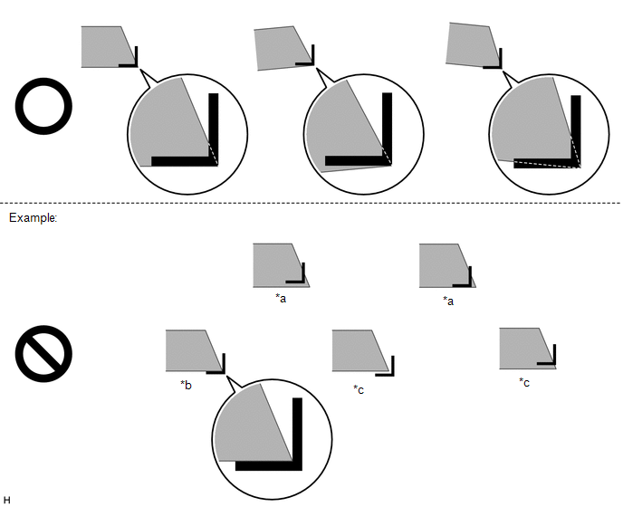
(1) Perform camera optical axis adjustment (high accuracy adjustment).
-
Move the adjustment mark (A) using the left, right, down and up buttons (B), (C), (D) and (E) to align the corner of the mark (A) with the upper left corner of the target bar.
Standard:
The outer corner of the mark (A) is aligned with the upper left corner of the target bar.
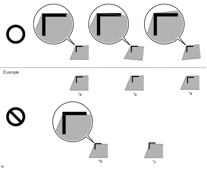
*a
Too Far Inside
*b
Inner Corner Contacting
*c
Too Far Outside
-
-
(2) Select "Next" on the "Back Camera Position Setting D (*) L_TOP" screen.
(e) Back Camera Position Setting (Lower Left Corner of Target Bar)
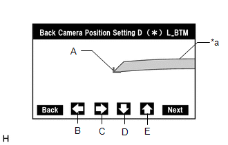
| *a | Target Bar for Back Camera Position Setting |
HINT:
- When the luggage compartment door is open, the "You can not calibrate the camera when the door is open. Please close the door." message will be displayed and camera position setting will not be possible.
-
If the "You can not calibrate the camera when the door is open. Please close the door." message is displayed even when the luggage compartment door is closed, perform inspections according to Problem Symptoms Table (When adjusting the camera optical axis, "You can not calibrate the camera when the door is open. Please close the door." is displayed even after the luggage compartment door has been closed).
Click here
(1) Perform camera optical axis adjustment (high accuracy adjustment).
-
Move the mark (A) using the left, right, down and up buttons (B), (C), (D) and (E) to align the outer corner of the mark (A) with the lower left corner of the target bar.
Standard:
The outer corner of the mark (A) is aligned with the lower left corner of the target bar.
*a
Too Far Inside
*b
Inner Corner Contacting
*c
Too Far Outside
-
-
(2) Select "Next" on the "Back Camera Position Setting D (*) L_BTM" screen.
(f) Back Camera Position Setting (Upper Right Corner of Target Bar)
| *a | Target Bar for Back Camera Position Setting |
HINT:
- When the luggage compartment door is open, the "You can not calibrate the camera when the door is open. Please close the door." message will be displayed and camera position setting will not be possible.
-
If the "You can not calibrate the camera when the door is open. Please close the door." message is displayed even when the luggage compartment door is closed, perform inspections according to Problem Symptoms Table (When adjusting the camera optical axis, "You can not calibrate the camera when the door is open. Please close the door." is displayed even after the luggage compartment door has been closed).
Click here
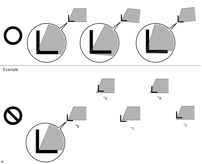
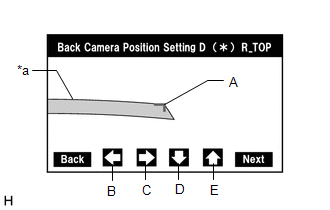
(1) Perform camera optical axis adjustment (high accuracy adjustment).
-
Move the mark (A) using the left, right, down and up buttons (B), (C), (D) and (E) to align the outer corner of the mark (A) with the upper right corner of the target bar.
Standard:
The outer corner of the mark (A) is aligned with the upper right corner of the target bar.
*a
Too Far Inside
*b
Inner Corner Contacting
*c
Too Far Outside
-
-
(2) Select "Next" on the "Back Camera Position Setting D (*) R_TOP" screen.
(g) Back Camera Position Setting (Lower Right Corner of Target Bar)
| *a | Target Bar for Back Camera Position Setting |
HINT:
- When the luggage compartment door is open, the "You can not calibrate the camera when the door is open. Please close the door." message will be displayed and camera position setting will not be possible.
-
If the "You can not calibrate the camera when the door is open. Please close the door." message is displayed even when the luggage compartment door is closed, perform inspections according to Problem Symptoms Table (When adjusting the camera optical axis, "You can not calibrate the camera when the door is open. Please close the door." is displayed even after the luggage compartment door has been closed).
Click here
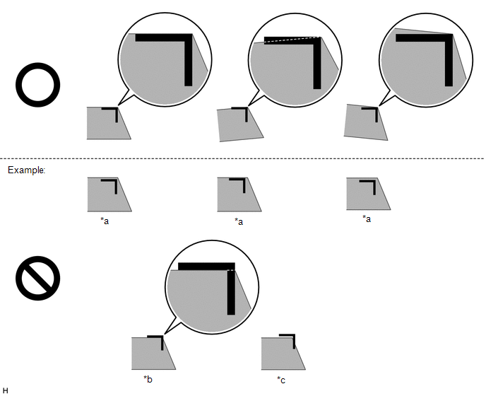
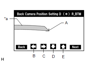
(1) Perform camera optical axis adjustment (high accuracy adjustment).
-
Move the mark (A) using the left, right, down and up buttons (B), (C), (D) and (E) to align the outer corner of the mark (A) with the lower right corner of the target bar.
Standard:
The outer corner of the mark (A) is aligned with the lower right corner of the target bar.
*a
Too Far Inside
*b
Inner Corner Contacting
*c
Too Far Outside
-
-
(2) Select "Next" on the "Back Camera Position Setting D (*) R_BTM" screen.
(h) Back Verify Mode
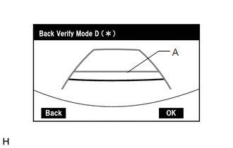
(1) Check that (A) and the target adjustment bar are overlapping.
- If the lines are not aligned, perform the "Steering Center Memorize" and "Max Steering Angle Memorize" operations.
- If (A) and the target adjustment bar are not aligned even if the tires are aligned straight ahead, perform the back camera position setting operation.
(2) Select "OK" to return to the "Mode Setting" screen and complete the adjustment.
HINT:
- The update is not completed until "OK" is selected.
- When "OK" is selected, a beep will sound to confirm that the adjustment values have been stored.
- The adjustment values are not stored until the beep has sounded.
(i) Finish diagnostic mode.
-
w/ Navigation system: Click here
-
w/o Navigation system: Click here
READ NEXT:
 Data List / Active Test
DATA LIST / ACTIVE TEST DATA LIST HINT: Using the Techstream to read the Data List allows the values or states of switches, sensors, actuators and other items to be read without removing any parts. Th
Diagnosis System
DIAGNOSIS SYSTEM PARKING ASSIST MONITOR DIAGNOSIS SYSTEM (a) For panoramic view monitor system diagnosis, signals received by the parking assist ECU can be checked, and the panoramic view monitor syst
Diagnostic Trouble Code Chart
DIAGNOSTIC TROUBLE CODE CHART Panoramic View Monitor System DTC No. Detection Item DTC Detection Condition Link C1611 ECU Malfunction When any of the following conditions is met:
E
SEE MORE:
Problem Symptoms Table
PROBLEM SYMPTOMS TABLE HINT:
Inspect the fuses and relays related to this system before inspecting the suspected areas below.
Use the table below to help determine the cause of problem symptoms. If multiple suspected areas are listed, the potential causes of the symptoms are listed in order of
Lost Communication with Multi-axis Acceleration Sensor Module Missing Message (U012587,U012687,U012987,U015587,U029387,U110687)
DESCRIPTION The forward recognition camera communicates with each sensor and ECU via CAN communication. If any malfunction is detected in a CAN communication circuit, one or more CAN communication system DTCs are stored. DTC No. Detection Item DTC Detection Condition Trouble Area MIL DT
