Lexus ES: Brake Warning Light Remains ON
DESCRIPTION
This procedure is for troubleshooting when the brake warning light / red (malfunction) remains on but no DTCs are output.
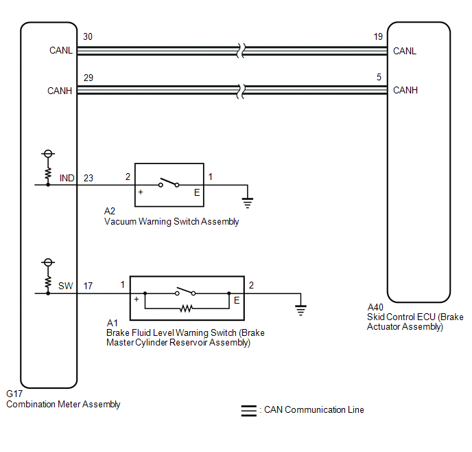
The skid control ECU (brake actuator assembly) controls the brake warning light / red (malfunction) in the combination meter assembly via CAN communication.
WIRING DIAGRAM
CAUTION / NOTICE / HINT
NOTICE:
-
After replacing the skid control ECU (brake actuator assembly), perform acceleration sensor zero point calibration and store system information memorization.
Click here
.gif)
- Before performing this procedure, depress the brake pedal and confirm that the stop lights illuminate.
PROCEDURE
| 1. | PRE-CHECK |
(a) Check that all of the following conditions required for the brake warning light / red (malfunction) to turn off are met:
(1) The ABS warning light are not illuminated.
HINT:
If the ABS warning light remains illuminated, make sure that the conditions required for the ABS warning light to turn off are met.
Click here
(2) The brake fluid level in the brake master cylinder reservoir assembly is not low.
(3) The vacuum inside the brake booster decreases.
HINT:
When the vacuum inside the brake booster decreases, the brake warning light / red (malfunction) comes on.
|

| 2. | CHECK VEHICLE CONTROL HISTORY (ELECTRONICALLY CONTROLLED BRAKE SYSTEM AND ELECTRIC PARKING BRAKE SYSTEM) |
(a) Connect the Techstream to the DLC3.
(b) Turn the engine switch on (IG).
(c) Enter the following menus: Chassis / Brake/EPB / Utility / Vehicle Control History (RoB).
(d) Using the Techstream, check for Vehicle Control History.
Click here
| Tester Display |
|---|
| Vehicle Control History (RoB) |
HINT:
If vehicle control history is stored when the electronically controlled brake system and electric parking brake system are suspended, the brake warning light / red (malfunction) illuminates.
| Result | Proceed to |
|---|---|
| There is no vehicle control history for when the electronically controlled brake system and electric parking brake system were suspended. | A |
| There is vehicle control history for when the electronically controlled brake system and/or electric parking brake system were suspended. | B |
| B |  | PERFORM TROUBLESHOOTING AND REPAIR REGARDING VEHICLE CONTROL HISTORY |
|
| 3. | INSPECT BRAKE MASTER CYLINDER RESERVOIR ASSEMBLY |
| (a) Make sure that there is no looseness at the locking part and the connecting part of the connector. OK: The connector is securely connected. |
|
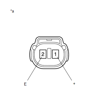
(b) Disconnect the A1 brake fluid level warning switch (brake master cylinder reservoir assembly) connector.
(c) Check both the connector case and the terminals for deformation and corrosion.
OK:
No deformation or corrosion.
(d) Measure the resistance according to the value(s) in the table below.
HINT:
A float is located inside the reservoir. Its position changes according to the brake fluid level.
Standard Resistance:
| Tester Connection | Condition | Specified Condition |
|---|---|---|
| 1 (+) - 2 (E) | Switch off (float up) | 1.9 to 2.1 kΩ |
| 1 (+) - 2 (E) | Switch on (float down) | Below 1 Ω |
(e) If there is no problem after finishing the above check, adjust the brake fluid level to the MAX level.
| NG | | REPLACE BRAKE MASTER CYLINDER RESERVOIR ASSEMBLY |
|
| 4. | CHECK HARNESS AND CONNECTOR (COMBINATION METER ASSEMBLY - BRAKE MASTER CYLINDER RESERVOIR ASSEMBLY) |
(a) Make sure that there is no looseness at the locking part and the connecting part of the connector.
OK:
The connector is securely connected.
(b) Disconnect the G17 combination meter assembly connector.
(c) Disconnect the A1 brake fluid level warning switch (brake master cylinder reservoir assembly) connector.
(d) Check both the connector case and the terminals for deformation and corrosion.
OK:
No deformation or corrosion.
(e) Measure the resistance according to the value(s) in the table below.
Standard Resistance:
| Tester Connection | Condition | Specified Condition |
|---|---|---|
| G17-17 (SW) - A1-1 (+) | Always | Below 1 Ω |
| G17-17 (SW) or A1-1 (+) - Body ground | Always | 10 kΩ or higher |
| A1-2 (E) - Body ground | Always | Below 1 Ω |
| NG | | REPAIR OR REPLACE HARNESS OR CONNECTOR |
|
| 5. | INSPECT VACUUM WARNING SWITCH ASSEMBLY |
(a) Inspect the vacuum warning switch assembly.
Click here
OK:
The vacuum warning switch assembly is normal.
| NG | | REPLACE VACUUM WARNING SWITCH ASSEMBLY |
|
| 6. | CHECK HARNESS AND CONNECTOR (COMBINATION METER ASSEMBLY - VACUUM WARNING SWITCH ASSEMBLY) |
(a) Make sure that there is no looseness at the locking part and the connecting part of the connector.
OK:
The connector is securely connected.
(b) Disconnect the G17 combination meter assembly connector.
(c) Disconnect the A2 vacuum warning switch assembly connector.
(d) Check both the connector case and the terminals for deformation and corrosion.
OK:
No deformation or corrosion.
(e) Measure the resistance according to the value(s) in the table below.
Standard Resistance:
| Tester Connection | Condition | Specified Condition |
|---|---|---|
| G17-23 (IND) - A2-2 (+) | Always | Below 1 Ω |
| G17-23 (IND) or A2-2 (+) - Body ground | Always | 10 kΩ or higher |
| A2-1 (E) - Body ground | Always | Below 1 Ω |
| NG | | REPAIR OR REPLACE HARNESS OR CONNECTOR |
|
| 7. | INSPECT COMBINATION METER ASSEMBLY |
(a) Connect the Techstream to the DLC3.
(b) Turn the engine switch on (IG).
(c) Enter the following menus: Body Electrical / Combination Meter / Active Test.
(d) Perform the Active Test of the combination meter assembly using the Techstream.
Click here
| Tester Display |
|---|
| Brake Warning |
(e) Check the combination meter assembly.
OK:
The brake warning light / red (malfunction) turns on or off in accordance with Techstream operation.
| OK | | REPLACE BRAKE ACTUATOR ASSEMBLY |
| NG | | INSPECT METER / GAUGE SYSTEM |
READ NEXT:
 Left Front Wheel ABS Hold Solenoid Control Circuit Short to Battery (C12A512,...,C12B049)
DESCRIPTION The ABS solenoid relay and solenoid valves are built into the brake actuator assembly. The front solenoid valve LH controls the brake fluid pressure of the front wheel cylinder LH of the v
Right Front Wheel ABS Hold Solenoid Control Circuit Short to Battery (C12BB12,...,C12C649)
DESCRIPTION The ABS solenoid relay and solenoid valves are built into the brake actuator assembly. The front solenoid valve RH controls the brake fluid pressure of the front wheel cylinder RH of the v
Left Rear Wheel ABS Hold Solenoid Control Circuit Short to Battery (C12D112,...,C12DC49)
DESCRIPTION The ABS solenoid relay and solenoid valves are built into the brake actuator assembly. The rear solenoid valve LH controls the brake fluid pressure of the rear wheel cylinder LH of the veh
SEE MORE:
Components
COMPONENTS ILLUSTRATION *A w/ Dust Cap - - *1 FUEL PRESSURE SENSOR (FUEL DELIVERY PIPE WITH SENSOR ASSEMBLY LH) *2 FUEL PIPE PLUG SUB-ASSEMBLY *3 DUST CAP SUB-ASSEMBLY *4 O-RING *5 NO. 1 FUEL INJECTOR BACK-UP RING *6 NO. 2 FUEL INJECTOR BACK-UP RING *7 N
Removal
REMOVAL CAUTION / NOTICE / HINT The necessary procedures (adjustment, calibration, initialization, or registration) that must be performed after parts are removed and installed, or replaced during side turn signal light assembly removal/installation are shown below. Necessary Procedure After Parts R
