
Lexus ES: Brake Vacuum Hose (for Gasoline Model)
Lexus ES (XZ10) Service Manual / Brake / Brake System (other) / Brake Vacuum Hose (for Gasoline Model)
Components
COMPONENTS
ILLUSTRATION
.png)
| *1 | FRONT CENTER UPPER SUSPENSION BRACE SUB-ASSEMBLY | - | - |
.png) | Tightening torque for "Major areas involving basic vehicle performance such as moving/turning/stopping" : N*m (kgf*cm, ft.*lbf) | .png) | N*m (kgf*cm, ft.*lbf): Specified torque |
| *T1 | Bolt color black: 8.0 N*m (82 kgf*cm, 71 in.*lbf) Bolt color silver: 8.9 N*m (91 kgf*cm, 79 in.*lbf) | - | - |
ILLUSTRATION
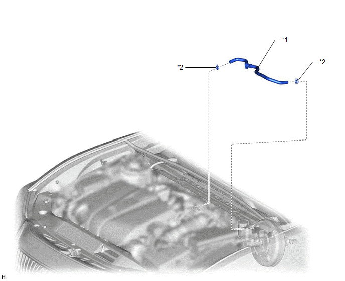
| *1 | UNION TO CHECK VALVE HOSE | *2 | CLIP |
ILLUSTRATION
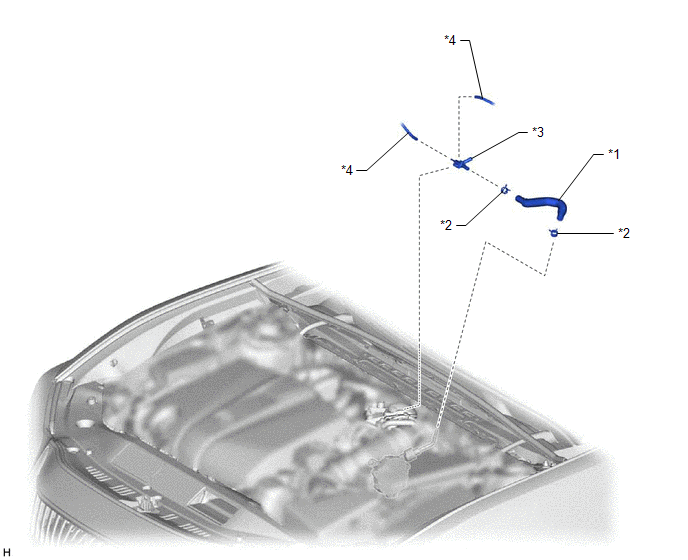
| *1 | AIR TUBE | *2 | CLIP |
| *3 | AIR DELIVERY WAY | *4 | VACUUM TRANSMITTING HOSE ASSEMBLY |
Removal
REMOVAL
CAUTION / NOTICE / HINT
Click here .gif)
READ NEXT:
 Components
COMPONENTS ILLUSTRATION *1 ENGINE WIRE *2 NO. 1 VACUUM HOSE CONNECTOR *3 VACUUM PUMP ASSEMBLY *4 NO. 1 VACUUM PUMP O-RING Tightening torque for "Major areas involving basic
Disassembly
DISASSEMBLY PROCEDURE 1. REMOVE END COVER (a) To prevent the coupling of the vacuum pump assembly from contacting the workbench, support the vacuum pump assembly with wooden blocks or an equivalent
SEE MORE:
Fail-safe Chart
FAIL-SAFE CHART FAIL-SAFE FUNCTION (a) When communication fails in any of the CAN bus lines (communication lines), a fail-safe function(s) will operate. The fail-safe function that is specified for each system operates to prevent those systems from malfunctioning. (b) The following table shows the e
Open in Master Reservoir Level Switch Circuit (C120F)
DESCRIPTION DTC No. Detection Item INF Code DTC Detection Condition Trouble Area MIL Note C120F Open in Master Reservoir Level Switch Circuit 371 The brake fluid level warning switch (brake booster with master cylinder assembly) circuit is open for 2 seconds or more.
Op
© 2016-2026 Copyright www.lexguide.net
