Lexus ES: Brake Switch "A" Circuit Open (P057113)
DESCRIPTION
The skid control ECU (brake actuator assembly) receives stop light switch assembly signals and uses them to determine whether or not the brakes are applied.
The skid control ECU (brake actuator assembly) has a detection circuit that it uses to detect an open in the stop light input line.
If the skid control ECU (brake actuator assembly) detects an open in this circuit, it will store this DTC.
| DTC No. | Detection Item | DTC Detection Condition | Trouble Area |
|---|---|---|---|
| P057113 | Brake Switch "A" Circuit Open | An open in the stop light switch assembly input line continues for 3 seconds or more. |
|
WIRING DIAGRAM
Refer to DTC P057111.
Click here .gif)
CAUTION / NOTICE / HINT
NOTICE:
After replacing the skid control ECU (brake actuator assembly), perform acceleration sensor zero point calibration and store system information memorization.
Click here
PROCEDURE
| 1. | CHECK HARNESS AND CONNECTOR (STOP LIGHT SWITCH ASSEMBLY OUTPUT CIRCUIT) |
| (a) Make sure that there is no looseness at the locking part and the connecting part of the connector. OK: The connector is securely connected. |
|
(b) Check both the connector case and the terminals for deformation and corrosion.
OK:
No deformation or corrosion.
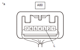
(c) Measure the voltage according to the value(s) in the table below.
Standard Voltage:
| Tester Connection | Condition | Specified Condition |
|---|---|---|
| A80-3 (L) - Body ground | Brake pedal depressed | 11 to 14 V |
| A80-3 (L) - Body ground | Brake pedal released | Below 1.5 V |
| NG |  | REPLACE STOP LIGHT SWITCH ASSEMBLY |
|

| 2. | CHECK HARNESS AND CONNECTOR (STOP LIGHT SWITCH ASSEMBLY INPUT CIRCUIT) |
| (a) Make sure that there is no looseness at the locking part and the connecting part of the connector. OK: The connector is securely connected. |
|
(b) Disconnect the A40 skid control ECU (brake actuator assembly) connector.
(c) Check both the connector case and the terminals for deformation and corrosion.
OK:
No deformation or corrosion.
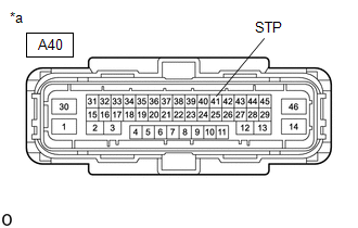
(d) Measure the voltage according to the value(s) in the table below.
Standard Voltage:
| Tester Connection | Condition | Specified Condition |
|---|---|---|
| A40-41 (STP) - Body ground | Brake pedal depressed | 11 to 14 V |
| OK | | REPLACE BRAKE ACTUATOR ASSEMBLY |
| NG | | REPAIR OR REPLACE HARNESS OR CONNECTOR |
READ NEXT:
 Parts Location
PARTS LOCATION ILLUSTRATION *A w/o AVS - - *1 FRONT AXLE HUB SUB-ASSEMBLY RH - FRONT SPEED SENSOR ROTOR RH *2 FRONT SPEED SENSOR RH *3 FRONT AXLE HUB SUB-ASSEMBLY LH - FRONT
Parts Location
PARTS LOCATION ILLUSTRATION *A w/o AVS *B for 2WD *C for AWD - - *1 FRONT AXLE HUB SUB-ASSEMBLY RH - FRONT SPEED SENSOR ROTOR RH *2 FRONT SPEED SENSOR RH *3 FRONT A
Precaution
PRECAUTION PRECAUTION FOR DISCONNECTING CABLE FROM NEGATIVE BATTERY TERMINAL NOTICE: When disconnecting the cable from the negative (-) battery terminal, initialize the following system(s) after the c
SEE MORE:
Precaution
PRECAUTION CAUTION:
Never perform work on fuel system components near any possible ignition sources.
Vaporized fuel could ignite, resulting in a serious accident.
Do not perform work on fuel system components without first disconnecting the cable from the negative (-) auxiliary battery termi
Diagnostic Trouble Code Chart
DIAGNOSTIC TROUBLE CODE CHART Power Mirror Control System (w/ Memory) DTC No. Detection Item Link U0142 Lost Communication with Main Body ECU
