Lexus ES: Back Camera Disconnected (C1622)
DESCRIPTION
This DTC is stored if the radio receiver assembly judges that the signals or signal lines between the rear television camera assembly and the multi-display assembly are not normal as a result of its self check.
| DTC No. | Detection Item | DTC Detection Condition | Trouble Area |
|---|---|---|---|
| C1622 | Back Camera Disconnected | Open or short in the rear television camera assembly signal circuit |
|
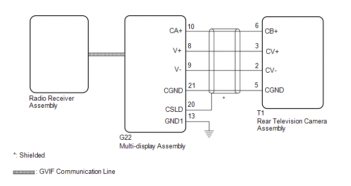
WIRING DIAGRAM
CAUTION / NOTICE / HINT
NOTICE:
-
If the cable was disconnected from and reconnected to the negative (-) battery terminal, the estimated course lines may not be displayed on the image of the area behind the vehicle. In this case, perform "Correct the Steering Angle Neutral Point".
Click here
.gif)
-
Depending on the parts that are replaced or operations that are performed during vehicle inspection or maintenance, calibration of other systems as well as the parking assist monitor system may be needed.
Click here
-
Depending on the parts that are replaced during vehicle inspection or maintenance, performing initialization, registration or calibration may be needed. Refer to Precaution for Audio and Visual System.
Click here
-
When replacing the radio receiver assembly, always replace it with a new one. If a radio receiver assembly which was installed to another vehicle is used, the following may occur:
- A communication malfunction DTC may be stored.
- The radio receiver assembly may not operate normally.
PROCEDURE
| 1. | CHECK DTC |
(a) Clear the DTCs.
Body Electrical > Navigation System > Clear DTCs(b) Turn the engine switch off.
(c) Turn the engine switch on (IG).
(d) Change the shift position to R and check for DTCs.
Body Electrical > Navigation System > Trouble CodesOK:
No DTCs are output.
| OK | .gif) | USE SIMULATION METHOD TO CHECK |
|
.gif)
| 2. | CHECK HARNESS AND CONNECTOR (REAR TELEVISION CAMERA ASSEMBLY - MULTI-DISPLAY ASSEMBLY) |
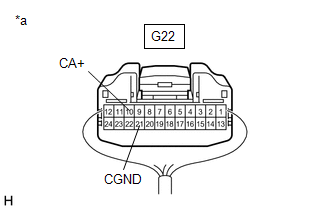
(a) Disconnect the G22 multi-display assembly connector.
(b) Disconnect the T1 rear television camera assembly connector.
(c) Measure the resistance according to the value(s) in the table below.
Standard Resistance:
| Tester Connection | Condition | Specified Condition |
|---|---|---|
| G22-10 (CA+) - T1-6 (CB+) | Always | Below 1 Ω |
| G22-8 (V+) - T1-3 (CV+) | Always | Below 1 Ω |
| G22-9 (V-) - T1-2 (CV-) | Always | Below 1 Ω |
| G22-21 (CGND) - T1-5 (CGND) | Always | Below 1 Ω |
| G22-10 (CA+) or T1-6 (CB+) - Body ground | Always | 10 kΩ or higher |
| G22-8 (V+) or T1-3 (CV+) - Body ground | Always | 10 kΩ or higher |
| G22-9 (V-) or T1-2 (CV-) - Body ground | Always | 10 kΩ or higher |
| G22-21 (CGND) or T1-5 (CGND) - Body ground | Always | 10 kΩ or higher |
| G22-20 (CSLD) - Body ground | Always | 10 kΩ or higher |
| NG | | REPAIR OR REPLACE HARNESS OR CONNECTOR |
|
| 3. | INSPECT MULTI-DISPLAY ASSEMBLY |
(a) Reconnect the G22 multi-display assembly connector.
| (b) Measure the resistance according to the value(s) in the table below. Standard Resistance:
|
|
(c) Measure the voltage according to the value(s) in the table below.
Standard Voltage:
| Tester Connection | Condition | Specified Condition |
|---|---|---|
| G22-10 (CA+) - G22-21 (CGND) | Engine switch on (ACC) | 5.5 to 7.05 V |
| NG | | REPLACE MULTI-DISPLAY ASSEMBLY |
|
| 4. | INSPECT MULTI-DISPLAY ASSEMBLY |
(a) Reconnect the T1 rear television camera assembly connector.
(b) Using an oscilloscope, check the waveform of the rear television camera assembly.
| *a | Component with harness connected (Multi-display Assembly) |
HINT:
A waterproof connector is used for the rear television camera assembly. Therefore, inspect the waveform at the multi-display assembly with the connector connected.
OK:
Waveform is similar to that shown in the illustration.
| Item | Content |
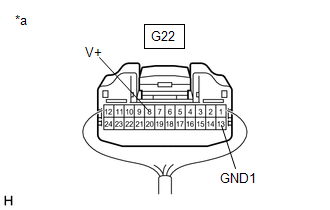
| Measurement terminal | G22-8 (V+) - G22-13 (GND1) |
| Measurement setting | 200 mV/DIV., 50 μs./DIV. |
| Condition | Engine switch on (IG), shift lever in R |
HINT:
- The video waveform changes according to the image sent by the rear television camera assembly.
- The video waveform is constantly output when the engine switch is on (ACC).
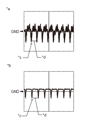
| *a | Waveform 1 (camera lens is not covered, displaying an image) |
| *b | Waveform 2 (camera lens is covered, blacking out the screen) |
| *c | Synchronization Signal |
| *d | Video Waveform |
| NG | | REPLACE REAR TELEVISION CAMERA ASSEMBLY |
|
| 5. | REPLACE MULTI-DISPLAY ASSEMBLY |
(a) Replace the multi-display assembly with a new or known good one.
Click here
|
| 6. | CHECK DTC OUTPUT |
(a) Clear the DTCs.
Body Electrical > Navigation System > Clear DTCs(b) Turn the engine switch off.
(c) Turn the engine switch on (IG).
(d) Change the shift position to R and check for DTCs.
Body Electrical > Navigation System > Trouble Codes| OK | | END |
| NG | | REPLACE RADIO RECEIVER ASSEMBLY |
READ NEXT:
 CD cannot be Ejected
CAUTION / NOTICE / HINT NOTICE:
Depending on the parts that are replaced during vehicle inspection or maintenance, performing initialization, registration or calibration may be needed. Refer to Pre
CD cannot be Inserted / Played or CD is Ejected Right After Insertion
CAUTION / NOTICE / HINT NOTICE:
Depending on the parts that are replaced during vehicle inspection or maintenance, performing initialization, registration or calibration may be needed. Refer to Pre
CD Sound Skips
CAUTION / NOTICE / HINT NOTICE:
Depending on the parts that are replaced during vehicle inspection or maintenance, performing initialization, registration or calibration may be needed. Refer to Pre
SEE MORE:
Hybrid/EV Battery Internal Electronic Failure (P31B549)
DESCRIPTION The battery ECU assembly monitors its internal operation and will store these DTCs when it detects an internal malfunction. DTC No. Detection Item DTC Detection Condition Trouble Area MIL Warning Indicate P31B549 Hybrid/EV Battery Internal Electronic Failure An abnor
Removal
REMOVAL CAUTION / NOTICE / HINT HINT:
Use the same procedure for the RH side and LH side.
The following procedure is for the LH side.
PROCEDURE 1. REMOVE LUGGAGE LOCK CONTROL CABLE PLATE Click here 2. REMOVE SWITCH BEZEL (w/ Power Trunk Lid System) Click here 3. REMOVE LUGGAGE COMPARTMEN
