Lexus ES: Adjustment
ADJUSTMENT
CAUTION / NOTICE / HINT
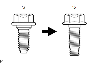
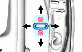
| *a | Centering Bolt |
| *b | Standard Bolt |
HINT:
- Use the same procedure for the RH side and LH side.
- The following procedure is for the LH side.
- Centering bolts are used to install the door hinges to the vehicle body and door. The door cannot be adjusted with the centering bolts installed. Substitute the centering bolts with standard bolts when making adjustments.
-
The specified torque for standard bolts is shown in the standard bolt chart.
Click here
.gif)
PROCEDURE
1. INSPECT FRONT DOOR
(a) Check that the clearance measurements of areas a through j are within each standard range.
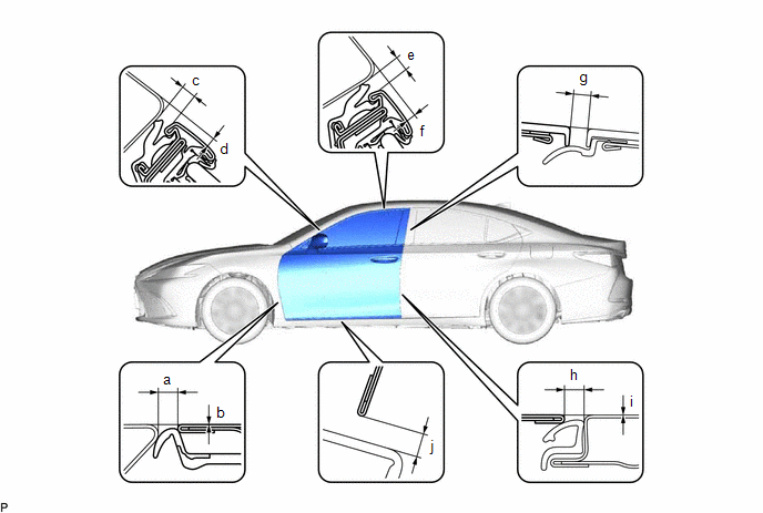 Standard Clearance
 | Area | Measurement | Area | Measurement |
|---|---|---|---|
| a | 2.9 to 5.9 mm (0.114 to 0.232 in.) | b | -1.5 to 1.5 mm (-0.0591 to 0.0591 in.) |
| c | 3.15 to 6.55 mm (0.124 to 0.258 in.) | d | 1.45 to 5.45 mm (0.0571 to 0.215 in.) |
| e | 3.15 to 6.55 mm (0.124 to 0.258 in.) | f | 1.45 to 5.45 mm (0.0571 to 0.215 in.) |
| g | 2.3 to 6.3 mm (0.0906 to 0.248 in.) | h | 3.0 to 5.4 mm (0.118 to 0.213 in.) |
| i | -1.2 to 1.2 mm (-0.0472 to 0.0472 in.) | j | 3.15 to 7.15 mm (0.124 to 0.281 in.) |
2. ADJUST FRONT DOOR
NOTICE:
Make sure to turn the engine switch (for Gasoline Model) or power switch (for HV Model) off before adjusting the door lock strikers.
| (a) Using SST, loosen the 4 hinge bolts on the vehicle body and adjust the door position. SST: 09812-00020 |
|
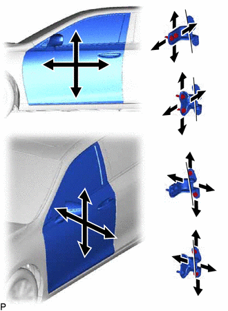
(b) Tighten the 4 hinge bolts on the vehicle body after adjustment.
Torque:
26 N·m {265 kgf·cm, 19 ft·lbf}
(c) Loosen the 4 hinge bolts on the door and adjust the door position.
(d) Tighten the 4 hinge bolts on the door after adjustment.
Torque:
26 N·m {265 kgf·cm, 19 ft·lbf}
| (e) Disengage the 4 claws to remove the front door lock striker cover. |
|
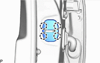
| (f) Using a T40 "TORX" socket wrench, slightly loosen the 2 striker mounting screws. |
|
(g) Using a brass bar and a hammer, hit the striker to adjust its position.
(h) Using a T40 "TORX" socket wrench, tighten the 2 striker mounting screws after adjustment.
Torque:
23 N·m {235 kgf·cm, 17 ft·lbf}
| (i) Engage the 4 claws to install the front door lock striker cover. |
|
READ NEXT:
 Reassembly
REASSEMBLY CAUTION / NOTICE / HINT HINT:
Use the same procedure for the RH side and LH side.
The following procedure is for the LH side.
PROCEDURE 1. PRECAUTION NOTICE: After turning the engin
Reassembly
REASSEMBLY CAUTION / NOTICE / HINT HINT:
Use the same procedure for the RH side and LH side.
The following procedure is for the LH side.
PROCEDURE 1. PRECAUTION NOTICE: After turning the engin
SEE MORE:
Data List / Active Test
DATA LIST / ACTIVE TEST READ DATA LIST HINT: Using the Techstream to read the Data List allows the values or states of switches, sensors, actuators and other items to be read without removing any parts. This non-intrusive inspection can be very useful because intermittent conditions or signals may b
Terminals Of Ecu
TERMINALS OF ECU CHECK VEHICLE APPROACHING SPEAKER CONTROLLER (a) Disconnect the G42 vehicle approaching speaker controller connector. (b) Measure the voltage and resistance according to the value(s) in the table below. Terminal No. (Symbol) Wiring Color Terminal Description Condition Sp
