Lexus ES: "CHK" message(s) are displayed on the SIGNAL CHECK screen.
DESCRIPTION
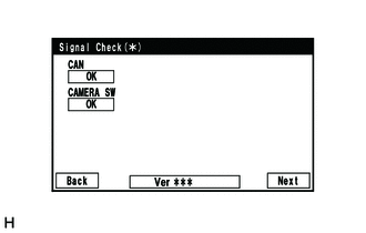
On the SIGNAL CHECK screen, it is possible to check if the signals sent to the parking assist ECU are normal.
Click here .gif)
HINT:
- On the SIGNAL CHECK screen, "OK" (blue) is displayed for items with a normal inspection result or input state.
- On the SIGNAL CHECK screen, "CHK" (red) is displayed for items with an abnormal inspection result or input state.
- Displayed items may differ depending on vehicle specifications.
| Item | Signal Input Method | Detail | DTC Output when Abnormal Result is Displayed | Signal Receiver |
|---|---|---|---|---|
| CAN | CAN communication | CAN communication signal | DTC is output | Related ECUs |
| SHIFT | Vehicle wire harness | Shift position switch signal | DTC is not output | BKUP LP relay |
| CAMERA SW | Vehicle wire harness | Panoramic view monitor switch signal input state | DTC is not output | Panoramic View Monitor Switch |
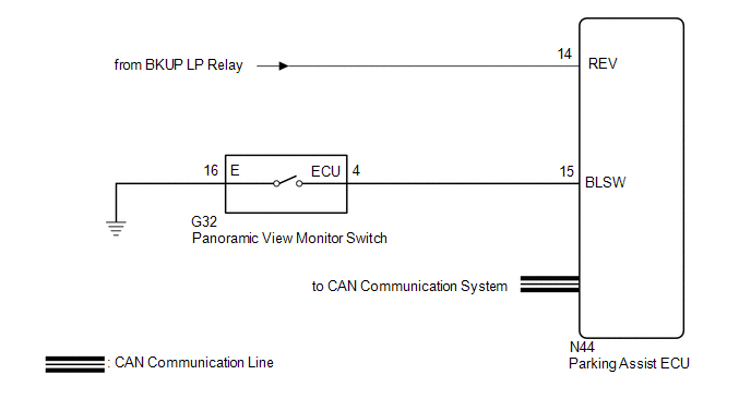
WIRING DIAGRAM
CAUTION / NOTICE / HINT
NOTICE:
-
When "!" is displayed on the multi-display assembly after the cable is disconnected from the negative (-) auxiliary battery terminal, correct the steering angle neutral point.
Click here
-
Depending on the parts that are replaced or operations that are performed during vehicle inspection or maintenance, calibration of other systems as well as the panoramic view monitor system may be needed.
Click here
PROCEDURE
| 1. | CHECK DISPLAY CHECK MODE |
| (a) Check which items display on the signal check screen. |
|
| Result | Proceed to |
|---|---|
| "CAMERA SW" displays "CHK" (red) | A |
| "CAN" displays "CHK" (red) | B |
| "SHIFT" displays "CHK" (red) | C |
| B |  | GO TO CAN COMMUNICATION SYSTEM |
| C | | GO TO STEP 4 |
|

| 2. | CHECK HARNESS AND CONNECTOR (PANORAMIC VIEW MONITOR SWITCH - PARKING ASSIST ECU AND BODY GROUND) |
(a) Disconnect the G32 panoramic view monitor switch connector.
(b) Disconnect the N44 parking assist ECU connector.
(c) Measure the resistance according to the value(s) in the table below.
Standard Resistance:
| Tester Connection | Condition | Specified Condition |
|---|---|---|
| N44-15 (BLSW) - G32-4 (ECU) | Always | Below 1 Ω |
| G32-2 (E) - Body ground | Always | Below 1 Ω |
| N44-15 (BLSW) or G32-4 (ECU) - Body ground | Always | 10 kΩ or higher |
| NG | | REPAIR OR REPLACE HARNESS OR CONNECTOR |
|
| 3. | INSPECT PANORAMIC VIEW MONITOR SWITCH |
(a) Remove the panoramic view monitor switch.
Click here
(b) Inspect the panoramic view monitor switch.
Click here
| OK | | REPLACE PARKING ASSIST ECU |
| NG | | REPLACE PANORAMIC VIEW MONITOR SWITCH |
| 4. | CHECK BACK-UP LIGHT |
(a) Check that the back-up light comes on.
OK:
The back-up light comes on.
| NG | | GO TO LIGHTING SYSTEM (EXT) |
|
| 5. | CHECK HARNESS AND CONNECTOR (REVERSE SIGNAL) |
(a) Disconnect the N44 parking assist ECU connector.
(b) Measure the voltage according to the value(s) in the table below.
Standard Voltage:
| Tester Connection | Condition | Specified Condition |
|---|---|---|
| N44-14 (REV) - Body ground | Power switch on (IG), shift lever in R | 11 to 14 V |
| N44-14 (REV) - Body ground | Power switch on (IG), shift lever not in R | Below 1 V |
| OK | | REPLACE PARKING ASSIST ECU |
| NG | | REPAIR OR REPLACE HARNESS OR CONNECTOR |
READ NEXT:
 BSM Buzzer Sound Request Signal Malfunction (C2A5C)
DESCRIPTION This DTC is stored when the rear television camera assembly receives an invalid communication signal from the blind spot monitor sensor RH. DTC No. Detection Item DTC Detection Cond
BSM Buzzer Malfunction (C2A5D)
DESCRIPTION This DTC is stored when the rear television camera assembly receives an RCTA buzzer circuit malfunction signal from the blind spot monitor sensor RH. DTC No. Detection Item DTC Dete
Back Camera Response Malfunction (C2A6A)
DESCRIPTION During self diagnosis of the parking assist ECU, the parking assist ECU sends display mode ID signals to the rear television camera assembly. This DTC is stored when the output of the rear
SEE MORE:
Initialization
INITIALIZATION NOTICE:
Initialization can be confirmed through the tire pressure warning light.
If the power switch is turned off during initialization, the tire pressure warning ECU and receiver memorizes that initialization was being performed. Therefore, it is not necessary to perform the in
Removal
REMOVAL CAUTION / NOTICE / HINT The necessary procedures (adjustment, calibration, initialization or registration) that must be performed after parts are removed and installed, or replaced during VSC OFF switch removal/installation are shown below. Necessary Procedures After Parts Removed/Installed/
