Lexus ES: Vehicle Speed Sensor "A" No Signal (P050031)
DESCRIPTION
The speed sensor detects the wheel speed and sends the appropriate signals to the skid control ECU. The skid control ECU converts these wheel speed signals into a pulse signal and outputs it to the ECM via the combination meter. The ECM determines the vehicle speed based on the frequency of this pulse signal.
| DTC No. | Detection Item | DTC Detection Condition | Trouble Area | MIL | Memory | Note |
|---|---|---|---|---|---|---|
| P050031 | Vehicle Speed Sensor "A" No Signal | All of the following conditions are met (1-trip detection logic):
|
| Comes on | DTC stored | SAE Code: P0500 |
| Vehicle Condition | |||||
|---|---|---|---|---|---|
| Pattern 1 | Pattern 2 | Pattern 3 | Pattern 4 | ||
| Diagnostic Condition | Park/neutral position switch D input signal is ON. | ○ | ○ | ○ | ○ |
| The counter gear speed is 300 rpm or more. | ○ | ○ | ○ | ○ | |
| When the vehicle is being driven in 1st gear, the transmission revolution sensor (NT) value is 1450 rpm or more. | ○ | - | - | - | |
| When the vehicle is being driven in 2nd gear, the transmission revolution sensor (NT) value is 840 rpm or more. | - | ○ | - | - | |
| When the vehicle is being driven in 3rd gear, the transmission revolution sensor (NT) value is 540 rpm or more. | - | - | ○ | - | |
| When the vehicle is being driven in 4th gear, the transmission revolution sensor (NT) value is 400 rpm or more. | - | - | - | ○ | |
| Malfunction Condition | No vehicle speed signal is transmitted to the ECM. | ○ | ○ | ○ | ○ |
| Duration | 2 seconds or more | 2 seconds or more | 2 seconds or more | 2 seconds or more | |
| Detection Logic | 1-trip detection logic | 1-trip detection logic | 1-trip detection logic | 1-trip detection logic | |
| Vehicle Condition | |||||
|---|---|---|---|---|---|
| Pattern 5 | Pattern 6 | Pattern 7 | Pattern 8 | ||
| Diagnostic Condition | Park/neutral position switch D input signal is ON. | ○ | ○ | ○ | ○ |
| The counter gear speed is 300 rpm or more. | ○ | ○ | ○ | ○ | |
| When the vehicle is being driven in 5th gear, the transmission revolution sensor (NT) value is 330 rpm or more. | ○ | - | - | - | |
| When the vehicle is being driven in 6th gear, the transmission revolution sensor (NT) value is 300 rpm or more. | - | ○ | - | - | |
| When the vehicle is being driven in 7th gear, the transmission revolution sensor (NT) value is 300 rpm or more. | - | - | ○ | - | |
| When the vehicle is being driven in 8th gear, the transmission revolution sensor (NT) value is 300 rpm or more. | - | - | - | ○ | |
| Malfunction Condition | No vehicle speed signal is transmitted to the ECM. | ○ | ○ | ○ | ○ |
| Duration | 2 seconds or more | 2 seconds or more | 2 seconds or more | 2 seconds or more | |
| Detection Logic | 1-trip detection logic | 1-trip detection logic | 1-trip detection logic | 1-trip detection logic | |
HINT:
This DTC is stored when any of the above detection patterns is met.
MONITOR DESCRIPTION
The ECM assumes that the vehicle is being driven when the transmission counter gear speed is 300 rpm or more. If there is no speed signal from the combination meter despite this condition being met, the ECM interprets this as a malfunction in the speed signal circuit, then illuminates the MIL and stores a DTC.
MONITOR STRATEGY
| Related DTCs | P0500: Vehicle speed sensor/Verify pulse input |
| Required sensors/components (Main) | Vehicle speed sensor, Combination meter, Skid control ECU |
| Required sensors/components (Sub) | Transmission revolution sensor (NT), ECT sensor |
| Frequency of operation | Continuous |
| Duration | 2 sec. |
| MIL operation | Immediately |
| Sequence operation | None |
TYPICAL ENABLING CONDITIONS
| The monitor will run whenever the following DTCs are not stored | None |
| Battery voltage | 8 V or more |
| Engine switch | On (IG) |
| Starter | OFF |
| Intermediate shaft speed sensor revolution | 300 rpm or more |
| Engine | Running |
| Shift change is completed before starting next shift change operation | - |
| R position switch | OFF |
| D position switch | ON |
| Park/neutral position switch (NSW) | OFF |
| Pressure control solenoid circuit fail (P08C1, P08C2, P0962, P0963, P0966, P0967, P0970, P0971, P2720, P2721, P2814, P2815, P281D, P281E) (Pending + MIL) | Not detected |
| Torque Converter Clutch Pressure Control Solenoid circuit fail (P2763, P2764) (Pending + MIL) | Not detected |
| Torque Converter Clutch Solenoid circuit fail (P2769, P2770) (Pending + MIL) | Not detected |
- Condition (A)
Condition (B)ECM selected gear
1st
Turbine speed sensor revolution
1450 rpm or more
Condition (C)ECM selected gear
2nd
Turbine speed sensor revolution
840 rpm or more
Condition (D)ECM selected gear
3rd
Turbine speed sensor revolution
540 rpm or more
Condition (E)ECM selected gear
4th
Turbine speed sensor revolution
400 rpm or more
Condition (F)ECM selected gear
5th
Turbine speed sensor revolution
330 rpm or more
Condition (G)ECM selected gear
6th
Turbine speed sensor revolution
300 rpm or more
Condition (H)ECM selected gear
7th
Turbine speed sensor revolution
300 rpm or more
ECM selected gear
8th
Turbine speed sensor revolution
300 rpm or more
- Condition (I)
Condition (J)ECT
20°C (68°F) or more
ECT sensor circuit fail (P0117, P0118)
(Pending + MIL)
Not detected
Time after park/neutral position switch ON to OFF
2 sec. or more
Either of the following conditions is met
(1) or (2)
(1) ECT
Less than 20°C (68°F)
(2) ECT sensor circuit fail (P0117, P0118)
(Pending + MIL)
Detected
Time after park/neutral position switch ON to OFF
30 sec. or more
TYPICAL MALFUNCTION THRESHOLDS
| Vehicle speed sensor signal | No signal |
CONFIRMATION DRIVING PATTERN
CAUTION:
When performing the confirmation driving pattern, obey all speed limits and traffic laws.
HINT:
- After repairs have been completed, clear the DTCs and then check that the vehicle has returned to normal by performing the following All Readiness check procedure.
-
When clearing the permanent DTCs, refer to the Clear Permanent DTC procedure.
Click here
.gif)
- Connect the Techstream to the DLC3.
- Turn the engine switch on (IG) and turn the Techstream on.
- Clear the DTCs (even if no DTCs are stored, perform the clear DTC procedure).
- Turn the engine switch off and wait for 2 minutes or more.
- Turn the engine switch on (IG) and turn the Techstream on.
- Start the engine.
-
Drive the vehicle at 13 km/h (8 mph) or more for a total of 2 seconds or more. [*1]
HINT:
[*1] : Normal judgment procedure.
The normal judgment procedure is used to complete DTC judgment and also used when clearing permanent DTCs.
- Stop the vehicle.
- Enter the following menus: Powertrain / Transmission / Utility / All Readiness.
- Input the DTC: P050031.
-
Check the DTC judgment result.
Techstream Display
Description
NORMAL
- DTC judgment completed
- System normal
ABNORMAL
- DTC judgment completed
- System abnormal
INCOMPLETE
- DTC judgment not completed
- Perform driving pattern after confirming DTC enabling conditions
N/A
- Unable to perform DTC judgment
- Number of DTCs which do not fulfill DTC preconditions has reached ECU memory limit
HINT:
- If the judgment result shows NORMAL, the system is normal.
- If the judgment result shows ABNORMAL, the system has a malfunction.
- If the judgment result shows INCOMPLETE or N/A, perform the normal judgment procedure again.
WIRING DIAGRAM
Refer to SFI system DTC P050031.
Click here
CAUTION / NOTICE / HINT
CAUTION:
-
Strictly observe posted speed, limits, traffic laws and road conditions.
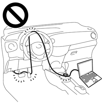
- Do not drive the vehicle with the cable of the Techstream contacting the pedals, shift lever or steering wheel.
- Driving the vehicle with the cable of the Techstream contacting these areas could impede vehicle control, resulting in a serious accident.
-
Do not operate the Techstream while driving the vehicle.
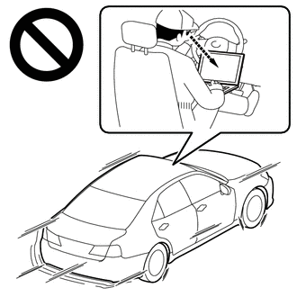
- Operating the Techstream while driving the vehicle will prevent you from paying sufficient attention to vehicle surroundings, and could result in a serious accident.
NOTICE:
-
Perform the universal trip to clear permanent DTCs.
Click here
-
Perform registration and/or initialization when parts related to the automatic transaxle are replaced.
Click here
PROCEDURE
| 1. | READ VALUE USING TECHSTREAM (VEHICLE SPEED) |
(a) Connect the Techstream to the DLC3.
(b) Turn the engine switch on (IG).
(c) Turn the Techstream on.
(d) Enter the following menus: Powertrain / Transmission / Data List / Vehicle Speed.
(e) Drive the vehicle.
(f) In accordance with the display on the Techstream, read the Data List.
Powertrain > Transmission > Data List| Tester Display | Measurement Item | Range | Normal Condition | Diagnostic Note |
|---|---|---|---|---|
| Vehicle Speed | Vehicle speed | Min.: 0 km/h (0 mph) Max.: 255 km/h (158 mph) | Actual vehicle speed |
|
| Tester Display |
|---|
| Vehicle Speed |
OK:
Vehicle speed displayed on the Techstream and speedometer display are equal.
| OK | .gif) | CHECK FOR INTERMITTENT PROBLEMS |
|
.gif)
| 2. | CHECK COMBINATION METER SYSTEM |
(a) Check the circuits that send vehicle speed signals to this system in the meter system.
Click here
(b) During inspection for the meter section, if there is an instruction that indicates to go back to inspections for each system, proceed to the next step.
|
| 3. | CHECK HARNESS AND CONNECTOR (COMBINATION METER ASSEMBLY - ECM) |
(a) Disconnect the G17 combination meter assembly connector.
(b) Disconnect the A25 ECM connector.
(c) Measure the resistance according to the value(s) in the table below.
Standard Resistance:
| Tester Connection | Condition | Specified Condition |
|---|---|---|
| G17-19 (+S) - A25-39 (SPD) | Always | Below 1 Ω |
| NG | | REPAIR OR REPLACE HARNESS OR CONNECTOR |
|
| 4. | REPLACE ECM |
(a) Replace the ECM.
Click here
| NEXT | | PERFORM REGISTRATION |
READ NEXT:
 System Voltage Circuit Short to Ground or Open (P056014)
DESCRIPTION The battery supplies electricity to the ECM even when the engine switch is off. This power allows the ECM to store data such as DTC history and freeze frame data. If the battery voltage fa
Starter Relay Circuit Short to Battery (P061512)
DESCRIPTION While the engine is being cranked, battery voltage is applied to terminal STA of the ECM. If the ECM detects the starter control (STA) signal while the vehicle is being driven, it determin
Brake Switch "B" Circuit Short to Battery (P070312)
DESCRIPTION The purpose of the stop light switch signal circuit is to prevent the engine from stalling when the brakes are suddenly applied while driving in the lock-up condition. When the brake pedal
SEE MORE:
Brake Switch "A" Circuit Open (P057113)
DESCRIPTION When the brakes are applied by the dynamic radar cruise control system, the skid control ECU (brake actuator assembly) operates the stop light switch assembly (stop light control relay) to illuminate the stop lights. If the ECM receives a signal from the skid control ECU (brake actuator
Motor/Generator Shutdown Signal (Hybrid/EV Side) Stuck Off (P33B99F)
DTC SUMMARY MALFUNCTION DESCRIPTION The hybrid vehicle control ECU detects malfunctions which prevent the inverter with converter assembly emergency shutdown circuit (HSDN) from shutting down the hybrid control system. Detection is performed when the power switch is turned on (IG) and during the shu
