Lexus ES: Vacuum Sensor
Components
COMPONENTS
ILLUSTRATION
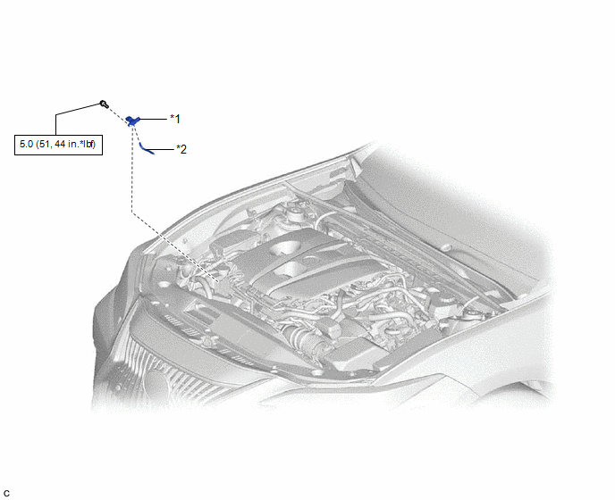
| *1 | E.F.I. VACUUM SENSOR ASSEMBLY (MANIFOLD ABSOLUTE PRESSURE SENSOR) | *2 | VACUUM HOSE |
.png) | N*m (kgf*cm, ft.*lbf): Specified torque | - | - |
Removal
REMOVAL
CAUTION / NOTICE / HINT
NOTICE:
This procedure includes the removal of small-head bolts. Refer to Small-Head Bolts of Basic Repair Hint to identify the small-head bolts.
Click here .gif)
PROCEDURE
1. REMOVE E.F.I. VACUUM SENSOR ASSEMBLY (MANIFOLD ABSOLUTE PRESSURE SENSOR)
| (a) Disconnect the E.F.I. vacuum sensor assembly (manifold absolute pressure sensor) connector. |
|
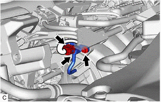
(b) Disconnect the vacuum hose from the E.F.I. vacuum sensor assembly (manifold absolute pressure sensor).
(c) Using an 8 mm socket wrench, remove the bolt and E.F.I. vacuum sensor assembly (manifold absolute pressure sensor) from the intake manifold.
Installation
INSTALLATION
CAUTION / NOTICE / HINT
NOTICE:
This procedure includes the installation of small-head bolts. Refer to Small-Head Bolts of Basic Repair Hint to identify the small-head bolts.
Click here .gif)
PROCEDURE
1. INSTALL E.F.I. VACUUM SENSOR ASSEMBLY (MANIFOLD ABSOLUTE PRESSURE SENSOR)
(a) Using an 8 mm socket wrench, install the E.F.I. vacuum sensor assembly (manifold absolute pressure sensor) to the intake manifold with the bolt.
Torque:
5.0 N·m {51 kgf·cm, 44 in·lbf}
(b) Connect the vacuum hose to the E.F.I. vacuum sensor assembly (manifold absolute pressure sensor).
(c) Connect the E.F.I. vacuum sensor assembly (manifold absolute pressure sensor) connector.
READ NEXT:
 Components
COMPONENTS ILLUSTRATION *1 AIR FUEL RATIO SENSOR *2 NO. 1 ENGINE COVER SUB-ASSEMBLY N*m (kgf*cm, ft.*lbf): Specified torque * For use with SST
SEE MORE:
Parts Location
PARTS LOCATION ILLUSTRATION *1 LUGGAGE DOOR OPENING CANCEL SWITCH ASSEMBLY *2 TRUNK AND FUEL SWITCH ASSEMBLY *3 LUGGAGE COMPARTMENT DOOR OPENING SWITCH *4 DLC3 *5 MAIN BODY ECU (MULTIPLEX NETWORK BODY ECU) *6 INSTRUMENT PANEL JUNCTION BLOCK ASSEMBLY - ECU-DCC NO. 2 FUSE
HD Radio Tuner Malfunction (B1551,B15A0,B15B3,B15B4,B15B7,B15BA,B15F9)
DESCRIPTION These DTCs are stored when a malfunction occurs in the radio receiver assembly. DTC No. Detection Item DTC Detection Condition Trouble Area B1551 HD Radio Tuner Malfunction When any of the following conditions is met:
"HD Radio" tuner decoder malfunction
"HD Radio"
