Lexus ES: Terminals Of Ecu
TERMINALS OF ECU
CHECK AIR CONDITIONING AMPLIFIER ASSEMBLY
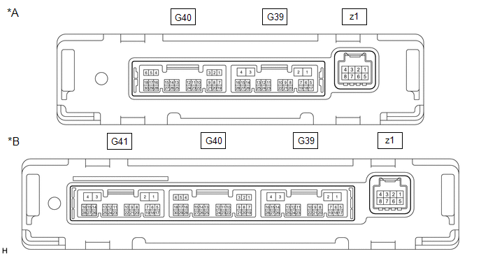
| *A | w/o Seat Heater | *B | w/ Seat Heater |
(a) Disconnect the G39 air conditioning amplifier assembly connector.
(b) Measure the voltage and resistance according to the value(s) in the table below.
HINT:
Measure the values on the wire harness side with the connector disconnected.
| Terminal No. (Symbol) | Wiring Color | Terminal Description | Condition | Specified Condition |
|---|---|---|---|---|
| G39-2 (IG+) - G39-4 (GND) | R - W-B | Power source (IG) | Engine switch on (IG) | 11 to 14 V |
| G39-2 (IG+) - G39-4 (GND) | R - W-B | Power source (IG) | Engine switch off | Below 1 V |
| G39-1 (B) - G39-4 (GND) | B - W-B | Battery power supply | Always | 11 to 14 V |
| G39-4 (GND) - Body ground | W-B - Body ground | Ground | Always | Below 1 Ω |
(c) Reconnect the G39 air conditioning amplifier assembly connector.
(d) Measure the voltage according to the value(s) in the table below.
| Terminal No. (Symbol) | Wiring Color | Terminal Description | Condition | Specified Condition |
|---|---|---|---|---|
| G39-5 (RDFG) - G39-4 (GND) | R - W-B | Rear window defogger signal | Engine switch on (IG), rear window defogger switch off | 11 to 14 V |
| G39-5 (RDFG) - G39-4 (GND) | R - W-B | Rear window defogger signal | Engine switch on (IG), rear window defogger switch on | Below 1 V |
| G39-14 (LIN1) - G39-4 (GND) | BE - W-B | LIN communication line | Engine switch on (IG) | Pulse generation |
CHECK REAR WINDOW DEFOGGER SWITCH (AIR CONDITIONING CONTROL ASSEMBLY)

(a) Disconnect the G23 air conditioning control assembly connector.
(b) Measure the voltage and resistance according to the value(s) in the table below.
HINT:
Measure the values on the wire harness side with the connector disconnected.
| Terminal No. (Symbol) | Wiring Color | Terminal Description | Condition | Specified Condition |
|---|---|---|---|---|
| G23-8 (IG+) - G23-4 (E) | R - W-B | Power source (IG) | Engine switch on (IG) | 11 to 14 V |
| G23-8 (IG+) - G23-4 (E) | R - W-B | Power source (IG) | Engine switch off | Below 1 V |
| G23-4 (GND) - Body ground | W-B - Body ground | Ground | Always | Below 1 Ω |
(c) Reconnect the G23 air conditioning control assembly connector.
(d) Check for pulses according to the value(s) in the table below.
| Terminal No. (Symbol) | Wiring Color | Terminal Description | Condition | Specified Condition |
|---|---|---|---|---|
| G23-3 (LIN1) - G23-4 (E) | LG - W-B | LIN communication line | Engine switch on (IG) | Pulse generation |
READ NEXT:
 Diagnosis System
DIAGNOSIS SYSTEM CHECK DLC3 (a) Check the DLC3. Click here INSPECT BATTERY VOLTAGE (a) Measure the battery voltage. Standard Voltage: 11 to 14 V If the voltage is below 11 V, recharge or replace th
Data List / Active Test
DATA LIST / ACTIVE TEST ACTIVE TEST HINT: Using the Techstream to perform Active Tests allows relays, VSVs, actuators and other items to be operated without removing any parts. This non-intrusive func
Rear Window Defogger System does not Operate
DESCRIPTION When the rear window defogger switch on the air conditioning control assembly is pressed, the operation signal is transmitted to the air conditioning amplifier assembly via LIN communicati
SEE MORE:
Dtc Check / Clear
DTC CHECK / CLEAR CHECK DTC (a) Connect the Techstream to the DLC3. (b) Turn the engine switch on (IG). (c) Turn the parking support brake system on. (d) Turn the Techstream on. (e) Enter the following menus: Body Electrical / Advanced Parking Guidance/ICS/Intuitive P/A / Trouble Codes. (f) Check fo
Removal
REMOVAL CAUTION / NOTICE / HINT The necessary procedures (adjustment, calibration, initialization or registration) that must be performed after parts are removed and installed, or replaced during sliding roof housing removal/installation are shown below. Necessary Procedure After Parts Removed/Insta
