Lexus ES: Rear Window Defogger System does not Operate
DESCRIPTION
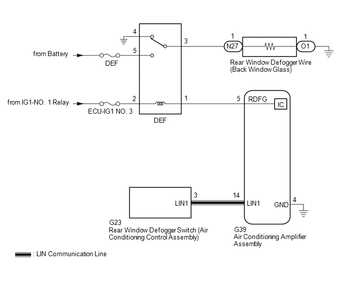
When the rear window defogger switch on the air conditioning control assembly is pressed, the operation signal is transmitted to the air conditioning amplifier assembly via LIN communication. When the air conditioning amplifier assembly receives the signal, it turns on the DEF relay to operate the window defogger system.
WIRING DIAGRAM
CAUTION / NOTICE / HINT
NOTICE:
- Inspect the fuses for circuits related to this system before performing the following procedure.
- If the battery voltage becomes low, battery load control will operate in order to ensure sufficient power is supplied to the power steering system. In this case, the window defogger system may not operate.
PROCEDURE
| 1. | CHECK AIR CONDITIONING SYSTEM |
(a) Check the air conditioning system.
HINT:
Both the window defogger system operation signal and air conditioning system operation signal are transmitted to the air conditioning amplifier assembly via the same communication line.
OK:
The air conditioning system operates normally.
| NG | .gif) | GO TO AIR CONDITIONING SYSTEM |
|
.gif)
| 2. | PERFORM ACTIVE TEST USING TECHSTREAM |
(a) Connect the Techstream to the DLC3.
(b) Turn the engine switch on (IG).
(c) Turn the Techstream on.
(d) Enter the following menus: Body Electrical / Air Conditioner / Active Test.
(e) Perform the Active Test according to the display on the Techstream.
Body Electrical > Air Conditioner > Active Test| Tester Display | Measurement Item | Control Range | Diagnostic Note |
|---|---|---|---|
| Defogger Relay (Rear) | Rear window defogger wire (Back window glass) | OFF or ON | - |
| Tester Display |
|---|
| Defogger Relay (Rear) |
OK:
The window defogger system operates normally.
| NG | | GO TO STEP 4 |
|
| 3. | REPLACE REAR WINDOW DEFOGGER SWITCH (AIR CONDITIONING CONTROL ASSEMBLY) |
(a) Replace the rear window defogger switch (air conditioning control assembly) with a new or known good one.
Click here .gif)
(b) Check that the window defogger system operates normally.
Click here
OK:
The window defogger system operates normally.
| OK | | END (REAR WINDOW DEFOGGER SWITCH (AIR CONDITIONING CONTROL ASSEMBLY) WAS DEFECTIVE) |
| NG | | REPLACE AIR CONDITIONING AMPLIFIER ASSEMBLY |
| 4. | INSPECT DEF RELAY |
(a) Inspect the DEF relay.
Click here
| NG | | REPLACE DEF RELAY |
|
| 5. | CHECK HARNESS AND CONNECTOR (DEF RELAY - IG1-NO. 1 RELAY AND BATTERY) |
| (a) Remove the DEF relay from the No. 1 engine room relay block and No. 1 junction block assembly. |
|
(b) Measure the voltage according to the value(s) in the table below.
Standard Voltage:
| Tester Connection | Condition | Specified Condition |
|---|---|---|
| DEF relay holder terminal 2 - Body ground | Engine switch on (IG) | 11 to 14 V |
| DEF relay holder terminal 5 - Body ground | Always | 11 to 14 V |
| NG | | REPAIR OR REPLACE HARNESS OR CONNECTOR |
|
| 6. | CHECK HARNESS AND CONNECTOR (DEF RELAY - AIR CONDITIONING AMPLIFIER ASSEMBLY) |
| (a) Remove the DEF relay from the No. 1 engine room relay block and No. 1 junction block assembly. |
|
(b) Disconnect the G39 air conditioning amplifier assembly connector.
(c) Measure the resistance according to the value(s) in the table below.
Standard Resistance:
| Tester Connection | Condition | Specified Condition |
|---|---|---|
| DEF relay holder terminal 1 - G39-5 (RDFG) | Always | Below 1 Ω |
| DEF relay holder terminal 1 or G39-5 (RDFG) - Body ground | Always | 10 kΩ or higher |
| NG | | REPAIR OR REPLACE HARNESS OR CONNECTOR |
|
| 7. | CHECK HARNESS AND CONNECTOR (DEF RELAY - REAR WINDOW DEFOGGER WIRE (BACK WINDOW GLASS)) |
| (a) Remove the DEF relay from the No. 1 engine room relay block and No. 1 junction block assembly. |
|
(b) Disconnect the N27 rear window defogger wire (back window glass) wire connector.
(c) Measure the resistance according to the value(s) in the table below.
Standard Resistance:
| Tester Connection | Condition | Specified Condition |
|---|---|---|
| DEF relay holder terminal 3 - N27-1 | Always | Below 1 Ω |
| DEF relay holder terminal 3 or N27-1 - Body ground | Always | 10 kΩ or higher |
| NG | | REPAIR OR REPLACE HARNESS OR CONNECTOR |
|
| 8. | CHECK HARNESS AND CONNECTOR (REAR WINDOW DEFOGGER WIRE (BACK WINDOW GLASS) - BODY GROUND) |
(a) Disconnect the O1 rear window defogger wire (back window glass) connector.
(b) Measure the resistance according to the value(s) in the table below.
Standard Resistance:
| Tester Connection | Condition | Specified Condition |
|---|---|---|
| O1-1 - Body ground | Always | Below 1 Ω |
| NG | | REPAIR OR REPLACE HARNESS OR CONNECTOR |
|
| 9. | CHECK AIR CONDITIONING AMPLIFIER ASSEMBLY |
| (a) Reconnect the G39 air conditioning amplifier assembly connector. |
|
(b) Reinstall the DEF relay.
(c) Remove the air conditioning amplifier assembly with its connectors still connected.
Click here
(d) Measure the voltage according to the value(s) in the table below.
Standard Voltage:
| Tester Connection | Condition | Specified Condition |
|---|---|---|
| G39-5 (RDFG) - G39-4 (GND) | Engine switch on (IG), rear window defogger switch on | Below 1 V |
| G39-5 (RDFG) - G39-4 (GND) | Engine switch on (IG), rear window defogger switch off | 11 to 14 V |
| OK | | REPAIR OR REPLACE BACK WINDOW GLASS |
| NG | | REPLACE AIR CONDITIONING AMPLIFIER ASSEMBLY |
READ NEXT:
 Precaution
PRECAUTION PRECAUTION FOR DISCONNECTING CABLE FROM NEGATIVE AUXILIARY BATTERY TERMINAL NOTICE: When disconnecting the cable from the negative (-) auxiliary battery terminal, initialize the following s
Parts Location
PARTS LOCATION ILLUSTRATION *1 DEF RELAY *2 REAR WINDOW DEFOGGER WIRE *3 NO. 1 ENGINE ROOM RELAY BLOCK AND NO. 1 JUNCTION BLOCK ASSEMBLY - DEF FUSE *4 BACK WINDOW GLASS ILLUSTRA
SEE MORE:
Open in One Side of Bus 4 Branch Line
DESCRIPTION When the CAN bus main lines are normal (no open, short to ground, short to +B or short between lines) and there is an ECU or sensor on the "Communication Bus Check" screen that is indicated as not communicating or whose connection status on the "Communication Bus Check" screen changes in
Operation Check
OPERATION CHECK AUTOMATIC LIGHT CONTROL SYSTEM OPERATION CHECK NOTICE: Make sure that the customize settings are set to default when performing the automatic light control system operation check. Click here (a) Turn the engine switch on (IG). (b) Turn the light control switch to the AUTO position.
