Lexus ES: Terminals Of Ecu
TERMINALS OF ECU
NOTICE:
-
After turning the power switch off, waiting time may be required before disconnecting the cable from the negative (-) auxiliary battery terminal. Therefore, make sure to read the disconnecting the cable from the negative (-) auxiliary battery terminal notices before proceeding with work.
Click here
.gif)
- Before measuring the resistance of the CAN bus, turn the power switch off and leave the vehicle for 1 minute or more without operating the key or any switches, or opening or closing the doors. After that, disconnect the cable from the negative (-) auxiliary battery terminal and leave the vehicle for 1 minute or more before measuring the resistance.
- This section describes the standard values for all CAN related components.
HINT:
-
The systems (ECUs and sensors) that use CAN communication vary depending on the vehicle and optional equipment. Check which systems (ECUs and sensors) are installed to the vehicle.
Click here
- Operating the power switch, any other switches or a door triggers related ECU and sensor communication on the CAN. This communication will cause the resistance value to change.
- Even after DTCs are cleared, if a DTC is stored again after driving the vehicle for a while, the malfunction may be occurring due to vibration of the vehicle. In such a case, wiggling the ECUs or wire harness while performing the inspection below may help determine the cause of the malfunction.
NO. 1 CAN JUNCTION CONNECTOR
(a) Check the No. 1 CAN junction connector.
(1) Connection diagram
.png)
| *a | Front view of wire harness connector (to No. 1 CAN Junction Connector) | *b | to Millimeter Wave Radar Sensor Assembly |
| *c | to Forward Recognition Camera | *d | to Central Gateway ECU (Network Gateway ECU) |
| *e | to Swing Grille Actuator Assembly | *f | to No. 6 CAN Junction Connector |
| *g | to Parking Assist ECU (w/ Panoramic View Monitor System) | *h | to Clearance Warning ECU Assembly (w/ Parking Support Alert System) |
(2) Check the connection diagram of the components which are connected to the No. 1 CAN junction connector.
| Terminal No. (Symbol) | Wiring Color | Connected to |
|---|---|---|
| A68-2 (CANH) | R | Millimeter wave radar sensor assembly (for Bus 1) |
| A68-12 (CANL) | W | |
| A68-3 (CANH) | L | Forward recognition camera (for Bus 1) |
| A68-13 (CANL) | W | |
| A68-4 (CANH) | P | Central gateway ECU (network gateway ECU) (for Bus 1) |
| A68-14 (CANL) | W | |
| A68-5 (CANH) | G | Swing grille actuator assembly (for Bus 1) |
| A68-15 (CANL) | W | |
| A68-6 (CANH) | B | No. 6 CAN junction connector (for Bus 1) |
| A68-16 (CANL) | W | |
| A68-7 (CANH) | GR | Parking assist ECU*1 (for Bus 1) |
| A68-17 (CANL) | W | |
| A68-8 (CANH) | LG | Clearance warning ECU assembly*2 (for Bus 1) |
| A68-18 (CANL) | W |
- *1: w/ Panoramic View Monitor System
- *2: w/ Parking Support Alert System
NO. 2 CAN JUNCTION CONNECTOR
(a) Check the No. 2 CAN junction connector.
(1) Connection diagram
.png)
| *a | Front view of wire harness connector (to No. 2 CAN Junction Connector) | *b | to Brake Booster with Master Cylinder Assembly |
| *c | to Airbag ECU Assembly | *d | to ECM |
| *e | to Rack and Pinion Power Steering Gear Assembly | *f | to No. 4 CAN Junction Connector |
| *g | to Brake Actuator Assembly | *h | to Hybrid Vehicle Control ECU |
(2) Check the connection diagram of the components which are connected to the No. 2 CAN junction connector.
| Terminal No. (Symbol) | Wiring Color | Connected to |
|---|---|---|
| A69-1 (CANH) | Y | Brake booster with master cylinder assembly (for Bus 4) |
| A69-11 (CANL) | W | |
| A69-2 (CANH) | R | Airbag ECU assembly (for Bus 4) |
| A69-12 (CANL) | W | |
| A69-3 (CANH) | P | ECM (for Bus 4) |
| A69-13 (CANL) | W | |
| A69-4 (CANH) | G | Rack and pinion power steering gear assembly (for Bus 4) |
| A69-14 (CANL) | W | |
| A69-5 (CANH) | GR | No. 4 CAN junction connector (for Bus 4) |
| A69-15 (CANL) | W | |
| A69-6 (CANH) | B | Brake actuator assembly (for Bus 4) |
| A69-16 (CANL) | W | |
| A69-7 (CANH) | G | Hybrid vehicle control ECU (for Bus 4) |
| A69-17 (CANL) | W |
NO. 4 CAN JUNCTION CONNECTOR
(a) Check the No. 4 CAN junction connector.
(1) Connection diagram
| *a | Front view of wire harness connector (to No. 4 CAN Junction Connector) | *b | to Central Gateway ECU (Network Gateway ECU) |
| *c | to Vehicle Approaching Speaker Controller | *d | to No. 2 CAN Junction Connector |
| *e | to Steering Sensor | *f | to DCM (Telematics Transceiver) (w/ Telematics Transceiver) |
| *g | to Option Connector (Bus Buffer ECU) (w/ CAN Compatible Optional Devices) | - | - |
(2) Check the connection diagram of the components which are connected to the No. 4 CAN junction connector.
| Terminal No. (Symbol) | Wiring Color | Connected to |
|---|---|---|
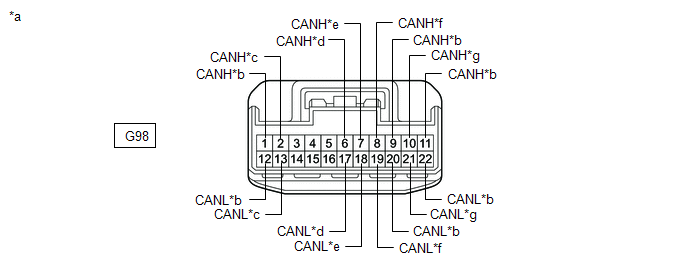
| G98-1 (CANH) | SB | Central gateway ECU (network gateway ECU) (for Bus 2) |
| G98-12 (CANL) | W | |
| G98-2 (CANH) | B | Vehicle approaching speaker controller (for Bus 2) |
| G98-13 (CANL) | W | |
| G98-6 (CANH) | SB | No. 2 CAN junction connector (for Bus 4) |
| G98-17 (CANL) | W | |
| G98-7 (CANH) | G | Steering sensor (for Bus 4) |
| G98-18 (CANL) | W | |
| G98-8 (CANH) | R | DCM (telematics transceiver)*1 (for Bus 3) |
| G98-19 (CANL) | W | |
| G98-9 (CANH) | B | Central gateway ECU (network gateway ECU) (for Bus 3) |
| G98-20 (CANL) | W | |
| G98-10 (CANH) | L | Option connector (bus buffer ECU)*2 (for Bus 3) |
| G98-21 (CANL) | W | |
| G98-11 (CANH) | G | Central gateway ECU (network gateway ECU) (for Bus 3) |
| G98-22 (CANL) | W |
- *1: w/ Telematics Transceiver
- *2: w/ CAN Compatible Optional Devices
(b) Check the No. 4 CAN junction connector.
(1) Connection diagram
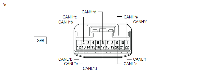
| *a | Front view of wire harness connector (to No. 4 CAN Junction Connector) | *b | to Radio Receiver Assembly |
| *c | to Stereo Component Equalizer Assembly | *d | to No. 7 CAN Junction Connector |
| *e | to Hybrid Vehicle Control ECU | *f | to No. 2 Junction Connector |
(2) Check the connection diagram of the components which are connected to the No. 4 CAN junction connector.
| Terminal No. (Symbol) | Wiring Color | Connected to |
|---|---|---|
| G99-1 (CANH) | B | Radio receiver assembly (for Bus 3) |
| G99-12 (CANL) | W | |
| G99-2 (CANH) | P | Stereo component equalizer assembly (for Bus 3) |
| G99-13 (CANL) | W | |
| G99-6 (CANH) | R | No. 7 CAN junction connector (for Bus 4) |
| G99-17 (CANL) | W | |
| G99-9 (CANH) | L | Hybrid vehicle control ECU (for Bus 2) |
| G99-20 (CANL) | W | |
| G99-11 (CANH) | G | No. 2 junction connector (for Bus 2) |
| G99-22 (CANL) | W |
NO. 5 CAN JUNCTION CONNECTOR
(a) Check the No. 5 CAN junction connector.
(1) Connection diagram
.png)
| *a | Front view of wire harness connector (to No. 5 CAN Junction Connector) | *b | to Air Conditioning Amplifier Assembly |
| *c | to Certification ECU (Smart Key ECU Assembly) | *d | to Headlight ECU Sub-assembly LH |
| *e | to Main Body ECU (Multiplex Network Body ECU) | *f | to No. 8 CAN Junction Connector |
| *g | to Combination Meter Assembly | *h | to Meter Mirror Sub-assembly (w/ Headup Display System) |
| *i | to Multiplex Tilt and Telescopic ECU (w/ Power Tilt and Power Telescopic System) | - | - |
(2) Check the connection diagram of the components which are connected to the No. 5 CAN junction connector.
| Terminal No. (Symbol) | Wiring Color | Connected to |
|---|---|---|
| G97-3 (CANH) | SB | Air conditioning amplifier assembly (for Bus 5) |
| G97-14 (CANL) | W | |
| G97-4 (CANH) | G | Certification ECU (smart key ECU assembly) (for Bus 5) |
| G97-15 (CANL) | W | |
| G97-5 (CANH) | R | Headlight ECU sub-assembly LH (for Bus 5) |
| G97-16 (CANL) | W | |
| G97-6 (CANH) | BE | Main body ECU (multiplex network body ECU) (for Bus 5) |
| G97-17 (CANL) | W | |
| G97-7 (CANH) | P | No. 8 CAN junction connector (for Bus 5) |
| G97-18 (CANL) | W | |
| G97-8 (CANH) | B | Combination meter assembly (for Bus 5) |
| G97-19 (CANL) | W | |
| G97-9 (CANH) | LG | Meter mirror sub-assembly*1 (for Bus 5) |
| G97-20 (CANL) | W | |
| G97-10 (CANH) | R | Multiplex tilt and telescopic ECU*2 (for Bus 5) |
| G97-21 (CANL) | W |
- *1: w/ Headup Display System
- *2: w/ Power Tilt and Power Telescopic System
NO. 6 CAN JUNCTION CONNECTOR
(a) Check the No. 6 CAN junction connector.
(1) Connection diagram
.png)
| *a | Front view of wire harness connector (to No. 6 CAN Junction Connector) | *b | to No. 1 CAN Junction Terminal |
| *c | to Blind Spot Monitor Sensor RH (w/ Blind Spot Monitor System) | *d | to Rear Television Camera Assembly |
| *e | to No. 1 CAN Junction Connector | - | - |
(2) Check the connection diagram of the components which are connected to the No. 6 CAN junction connector.
| Terminal No. (Symbol) | Wiring Color | Connected to |
|---|---|---|
| N98-1 (CANH) | GR | No. 1 CAN junction terminal (for Bus 1) |
| N98-11 (CANL) | W | |
| N98-3 (CANH) | BE | Blind spot monitor sensor RH* (for Bus 1) |
| N98-13 (CANL) | W | |
| N98-4 (CANH) | R | Rear television camera assembly (for Bus 1) |
| N98-14 (CANL) | W | |
| N98-5 (CANH) | B | No. 1 CAN junction connector (for Bus 1) |
| N98-15 (CANL) | W |
- *: w/ Blind Spot Monitor System
NO. 7 CAN JUNCTION CONNECTOR
(a) Check the No. 7 CAN junction connector.
(1) Connection diagram
.png)
| *a | Front view of wire harness connector (to No. 7 CAN Junction Connector) | *b | to Tire Pressure Warning ECU and Receiver |
| *c | to Occupant Detection ECU | *d | to Central Gateway ECU (Network Gateway ECU) |
| *e | to No. 4 CAN Junction Connector | - | - |
(2) Check the connection diagram of the components which are connected to the No. 7 CAN junction connector.
| Terminal No. (Symbol) | Wiring Color | Connected to |
|---|---|---|
| N99-1 (CANH) | L | Tire pressure warning ECU and receiver (for Bus 4) |
| N99-7 (CANL) | W | |
| N99-2 (CANH) | GR | Occupant detection ECU (for Bus 4) |
| N99-8 (CANL) | W | |
| N99-3 (CANH) | G | Central gateway ECU (network gateway ECU) (for Bus 4) |
| N99-9 (CANL) | W | |
| N99-4 (CANH) | LG | No. 4 CAN junction connector (for Bus 4) |
| N99-10 (CANL) | W |
NO. 8 CAN JUNCTION CONNECTOR
(a) Check the No. 8 CAN junction connector.
(1) Connection diagram
.png)
| *a | Front view of wire harness connector (to No. 8 CAN Junction Connector) | *b | to Outer Mirror Control ECU Assembly LH (w/ Seat Position Memory System) |
| *c | to Luggage Closer Motor Assembly (w/ Power Trunk Lid System) | *d | to No. 5 CAN Junction Connector |
| *e | to No. 1 Junction Connector | *f | to Position Control ECU Assembly LH (w/ Seat Position Memory System) |
(2) Check the connection diagram of the components which are connected to the No. 8 CAN junction connector.
| Terminal No. (Symbol) | Wiring Color | Connected to |
|---|---|---|
| N101-1 (CANH) | LG | Outer mirror control ECU assembly LH*1 (for Bus 5) |
| N101-7 (CANL) | W | |
| N101-2 (CANH) | P | Luggage closer motor assembly*2 (for Bus 5) |
| N101-8 (CANL) | W | |
| N101-3 (CANH) | B | No. 5 CAN junction connector (for Bus 5) |
| N101-9 (CANL) | W | |
| N101-4 (CANH) | B | No. 1 junction connector (for Bus 5) |
| N101-10 (CANL) | W | |
| N101-5 (CANH) | G | Position control ECU assembly LH*1 (for Bus 5) |
| N101-11 (CANL) | W |
- *1: w/ Seat Position Memory System
- *2: w/ Power Trunk Lid System
NO. 1 JUNCTION CONNECTOR
(a) Check the No. 1 junction connector.
(1) Connection diagram
.png)
| *a | Front view of wire harness connector (to No. 1 Junction Connector) | *b | to Central Gateway ECU (Network Gateway ECU) |
| *c | to Headlight ECU Sub-assembly RH | *d | to Outer Mirror Control ECU Assembly RH (w/ Seat Position Memory System) |
| *e | to No. 8 CAN Junction Connector | - | - |
(2) Check the connection diagram of the components which are connected to the No. 1 junction connector.
| Terminal No. (Symbol) | Wiring Color | Connected to |
|---|---|---|
| N97-8 (CANH) | G | Central gateway ECU (network gateway ECU) (for Bus 5) |
| N97-19 (CANL) | W | |
| N97-9 (CANH) | G | Headlight ECU sub-assembly RH (for Bus 5) |
| N97-20 (CANL) | W | |
| N97-10 (CANH) | GR | Outer mirror control ECU assembly RH* (for Bus 5) |
| N97-21 (CANL) | W | |
| N97-11 (CANH) | B | No. 8 CAN junction connector (for Bus 5) |
| N97-22 (CANL) | W |
- *: w/ Seat Position Memory System
NO. 2 JUNCTION CONNECTOR
(a) Check the No. 2 junction connector.
(1) Connection diagram
.png)
| *a | Front view of wire harness connector (to No. 2 Junction Connector) | *b | to No. 4 CAN Junction Connector |
| *c | to Brake Booster with Master Cylinder Assembly | *d | to Inverter with Converter Assembly |
| *e | to ECM | - | - |
(2) Check the connection diagram of the components which are connected to the No. 2 junction connector.
| Terminal No. (Symbol) | Wiring Color | Connected to |
|---|---|---|
| A71-8 (CANH) | L | No. 4 CAN junction connector (for Bus 2) |
| A71-19 (CANL) | W | |
| A71-9 (CANH) | LG | Brake booster with master cylinder assembly (for Bus 2) |
| A71-20 (CANL) | W | |
| A71-10 (CANH) | V | Inverter with converter assembly (for Bus 2) |
| A71-21 (CANL) | W | |
| A71-11 (CANH) | B | ECM (for Bus 2) |
| A71-22 (CANL) | W |
NO. 1 CAN JUNCTION TERMINAL
(a) Check the No. 1 CAN junction terminal.
(1) Connection diagram

| *a | Front view of wire harness connector (to No. 1 CAN Junction Terminal) | *b | to No. 6 CAN Junction Connector |
(2) Check the connection diagram of the components which are connected to the No. 1 CAN junction terminal.
| Terminal No. (Symbol) | Wiring Color | Connected to |
|---|---|---|
| N105-3 (CANH) | GR | No. 6 CAN junction connector (for Bus 1) |
| N105-2 (CANL) | W |
DLC3
(a) Disconnect the cable from the negative (-) auxiliary battery terminal.
(b) Measure the resistance according to the value(s) in the table below.
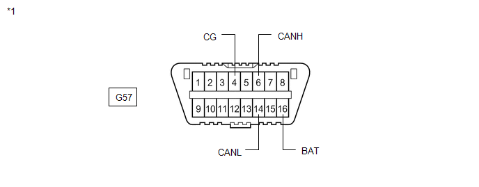
| *1 | DLC3 | - | - |
Standard Resistance:
| Terminal No. (Symbol) | Wiring Color | Terminal Description | Condition | Specified Condition |
|---|---|---|---|---|
| G57-6 (CANH) - G57-14 (CANL) | B - W | HIGH-level CAN bus line - LOW-level CAN bus line | Cable disconnected from negative (-) auxiliary battery terminal | 54 to 69 Ω |
| G57-6 (CANH) - G57-4 (CG) | B - W-B | HIGH-level CAN bus line - Ground | Cable disconnected from negative (-) auxiliary battery terminal | 200 Ω or higher |
| G57-14 (CANL) - G57-4 (CG) | W - W-B | LOW-level CAN bus line - Ground | Cable disconnected from negative (-) auxiliary battery terminal | 200 Ω or higher |
| G57-6 (CANH) - G57-16 (BAT) | B - R | HIGH-level CAN bus line - Auxiliary battery positive (+) | Cable disconnected from negative (-) auxiliary battery terminal | 6 kΩ or higher |
| G57-14 (CANL) - G57-16 (BAT) | W - R | LOW-level CAN bus line - Auxiliary battery positive (+) | Cable disconnected from negative (-) auxiliary battery terminal | 6 kΩ or higher |
CENTRAL GATEWAY ECU (NETWORK GATEWAY ECU)
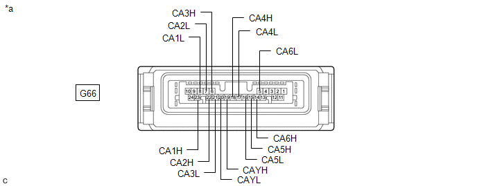
| *a | Component without harness connected (Central Gateway ECU (Network Gateway ECU)) | - | - |
(a) Disconnect the cable from the negative (-) auxiliary battery terminal.
(b) Disconnect the G66 central gateway ECU (network gateway ECU) connector.
(c) Measure the resistance according to the value(s) in the table below.
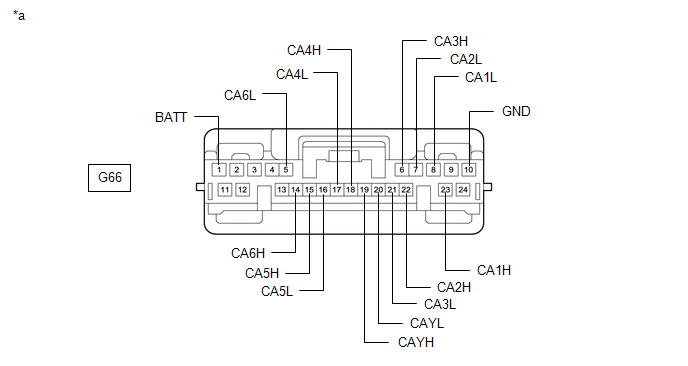
| *a | Front view of wire harness connector (to Central Gateway ECU (Network Gateway ECU)) | - | - |
Standard Resistance:
Diagnosis Bus Branch Lines (DLC3 - Central gateway ECU (network gateway ECU))| Terminal No. (Symbol) | Wiring Color | Terminal Description | Condition | Specified Condition |
|---|---|---|---|---|
| G66-14 (CA6H) - G66-5 (CA6L) | B - W | HIGH-level CAN bus line - LOW-level CAN bus line | Cable disconnected from negative (-) auxiliary battery terminal | 1 MΩ or higher |
| G66-14 (CA6H) - G66-10 (GND) | B - W-B | HIGH-level CAN bus line - Ground | Cable disconnected from negative (-) auxiliary battery terminal | 200 Ω or higher |
| G66-5 (CA6L) - G66-10 (GND) | W - W-B | LOW-level CAN bus line - Ground | Cable disconnected from negative (-) auxiliary battery terminal | 200 Ω or higher |
| G66-14 (CA6H) - G66-1 (BATT) | B - BE | HIGH-level CAN bus line - Auxiliary battery positive (+) | Cable disconnected from negative (-) auxiliary battery terminal | 6 kΩ or higher |
| G66-5 (CA6L) - G66-1 (BATT) | W - BE | LOW-level CAN bus line - Auxiliary battery positive (+) | Cable disconnected from negative (-) auxiliary battery terminal | 6 kΩ or higher |
| Terminal No. (Symbol) | Wiring Color | Terminal Description | Condition | Specified Condition |
|---|---|---|---|---|
| G66-23 (CA1H) - G66-8 (CA1L) | B - W | HIGH-level CAN bus line - LOW-level CAN bus line | Cable disconnected from negative (-) auxiliary battery terminal | 108 to 132 Ω |
| G66-23 (CA1H) - G66-10 (GND) | B - W-B | HIGH-level CAN bus line - Ground | Cable disconnected from negative (-) auxiliary battery terminal | 200 Ω or higher |
| G66-8 (CA1L) - G66-10 (GND) | W - W-B | LOW-level CAN bus line - Ground | Cable disconnected from negative (-) auxiliary battery terminal | 200 Ω or higher |
| G66-23 (CA1H) - G66-1 (BATT) | B - BE | HIGH-level CAN bus line - Auxiliary battery positive (+) | Cable disconnected from negative (-) auxiliary battery terminal | 6 kΩ or higher |
| G66-8 (CA1L) - G66-1 (BATT) | W - BE | LOW-level CAN bus line - Auxiliary battery positive (+) | Cable disconnected from negative (-) auxiliary battery terminal | 6 kΩ or higher |
| Terminal No. (Symbol) | Wiring Color | Terminal Description | Condition | Specified Condition |
|---|---|---|---|---|
| G66-18 (CA4H) - G66-17 (CA4L) | SB - W | HIGH-level CAN bus line - LOW-level CAN bus line | Cable disconnected from negative (-) auxiliary battery terminal | 108 to 132 Ω |
| G66-18 (CA4H) - G66-10 (GND) | SB - W-B | HIGH-level CAN bus line - Ground | Cable disconnected from negative (-) auxiliary battery terminal | 200 Ω or higher |
| G66-17 (CA4L) - G66-10 (GND) | W - W-B | LOW-level CAN bus line - Ground | Cable disconnected from negative (-) auxiliary battery terminal | 200 Ω or higher |
| G66-18 (CA4H) - G66-1 (BATT) | SB - BE | HIGH-level CAN bus line - Auxiliary battery positive (+) | Cable disconnected from negative (-) auxiliary battery terminal | 6 kΩ or higher |
| G66-17 (CA4L) - G66-1 (BATT) | W - BE | LOW-level CAN bus line - Auxiliary battery positive (+) | Cable disconnected from negative (-) auxiliary battery terminal | 6 kΩ or higher |
| Terminal No. (Symbol) | Wiring Color | Terminal Description | Condition | Specified Condition |
|---|---|---|---|---|
| G66-6 (CA3H) - G66-19 (CAYH) | B - G | HIGH-level CAN bus line - HIGH-level CAN bus line | Cable disconnected from negative (-) auxiliary battery terminal | Below 1 Ω |
| G66-21 (CA3L) - G66-20 (CAYL) | W - W | LOW-level CAN bus line - LOW-level CAN bus line | Cable disconnected from negative (-) auxiliary battery terminal | Below 1 Ω |
| G66-6 (CA3H) - G66-10 (GND) | B - W-B | HIGH-level CAN bus line - Ground | Cable disconnected from negative (-) auxiliary battery terminal | 200 Ω or higher |
| G66-21 (CA3L) - G66-10 (GND) | W - W-B | LOW-level CAN bus line - Ground | Cable disconnected from negative (-) auxiliary battery terminal | 200 Ω or higher |
| G66-6 (CA3H) - G66-1 (BATT) | B - BE | HIGH-level CAN bus line - Auxiliary battery positive (+) | Cable disconnected from negative (-) auxiliary battery terminal | 6 kΩ or higher |
| G66-21 (CA3L) - G66-1 (BATT) | W - BE | LOW-level CAN bus line - Auxiliary battery positive (+) | Cable disconnected from negative (-) auxiliary battery terminal | 6 kΩ or higher |
| Terminal No. (Symbol) | Wiring Color | Terminal Description | Condition | Specified Condition |
|---|---|---|---|---|
| G66-22 (CA2H) - G66-7 (CA2L) | G - W | HIGH-level CAN bus line - LOW-level CAN bus line | Cable disconnected from negative (-) auxiliary battery terminal | 108 to 132 Ω |
| G66-22 (CA2H) - G66-10 (GND) | G - W-B | HIGH-level CAN bus line - Ground | Cable disconnected from negative (-) auxiliary battery terminal | 200 Ω or higher |
| G66-7 (CA2L) - G66-10 (GND) | W - W-B | LOW-level CAN bus line - Ground | Cable disconnected from negative (-) auxiliary battery terminal | 200 Ω or higher |
| G66-22 (CA2H) - G66-1 (BATT) | G - BE | HIGH-level CAN bus line - Auxiliary battery positive (+) | Cable disconnected from negative (-) auxiliary battery terminal | 6 kΩ or higher |
| G66-7 (CA2L) - G66-1 (BATT) | W - BE | LOW-level CAN bus line - Auxiliary battery positive (+) | Cable disconnected from negative (-) auxiliary battery terminal | 6 kΩ or higher |
| Terminal No. (Symbol) | Wiring Color | Terminal Description | Condition | Specified Condition |
|---|---|---|---|---|
| G66-15 (CA5H) - G66-16 (CA5L) | LG - W | HIGH-level CAN bus line - LOW-level CAN bus line | Cable disconnected from negative (-) auxiliary battery terminal | 108 to 132 Ω |
| G66-15 (CA5H) - G66-10 (GND) | LG - W-B | HIGH-level CAN bus line - Ground | Cable disconnected from negative (-) auxiliary battery terminal | 200 Ω or higher |
| G66-16 (CA5L) - G66-10 (GND) | W - W-B | LOW-level CAN bus line - Ground | Cable disconnected from negative (-) auxiliary battery terminal | 200 Ω or higher |
| G66-15 (CA5H) - G66-1 (BATT) | LG - BE | HIGH-level CAN bus line - Auxiliary battery positive (+) | Cable disconnected from negative (-) auxiliary battery terminal | 6 kΩ or higher |
| G66-16 (CA5L) - G66-1 (BATT) | W - BE | LOW-level CAN bus line - Auxiliary battery positive (+) | Cable disconnected from negative (-) auxiliary battery terminal | 6 kΩ or higher |
STEERING SENSOR
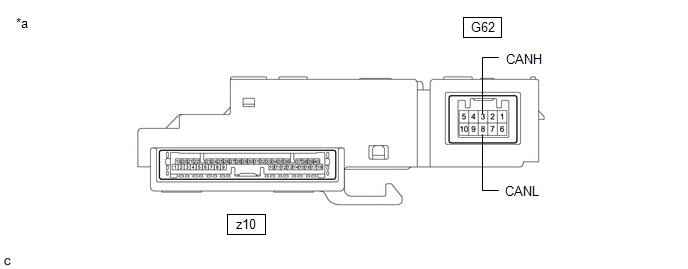
| *a | Component without harness connected (Steering Sensor) | - | - |
(a) Disconnect the cable from the negative (-) auxiliary battery terminal.
(b) Disconnect the G62 steering sensor connector.
(c) Measure the resistance according to the value(s) in the table below.
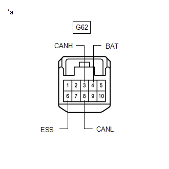
| *a | Front view of wire harness connector (to Steering Sensor) |
Standard Resistance:
| Terminal No. (Symbol) | Wiring Color | Terminal Description | Condition | Specified Condition |
|---|---|---|---|---|
| G62-3 (CANH) - G62-8 (CANL) | G - W | HIGH-level CAN bus line - LOW-level CAN bus line | Cable disconnected from negative (-) auxiliary battery terminal | 54 to 69 Ω |
| G62-3 (CANH) - G62-6 (ESS) | G - W-B | HIGH-level CAN bus line - Ground | Cable disconnected from negative (-) auxiliary battery terminal | 200 Ω or higher |
| G62-8 (CANL) - G62-6 (ESS) | W - W-B | LOW-level CAN bus line - Ground | Cable disconnected from negative (-) auxiliary battery terminal | 200 Ω or higher |
| G62-3 (CANH) - G62-4 (BAT) | G - GR | HIGH-level CAN bus line - Auxiliary battery positive (+) | Cable disconnected from negative (-) auxiliary battery terminal | 6 kΩ or higher |
| G62-8 (CANL) - G62-4 (BAT) | W - GR | LOW-level CAN bus line - Auxiliary battery positive (+) | Cable disconnected from negative (-) auxiliary battery terminal | 6 kΩ or higher |
HYBRID VEHICLE CONTROL ECU
Refer to Terminals of ECU.
Click here
(a) Disconnect the cable from the negative (-) auxiliary battery terminal.
(b) Disconnect the G60 hybrid vehicle control ECU connector.
(c) Measure the resistance according to the value(s) in the table below.
Standard Resistance:
Bus 2 Branch Lines| Terminal No. (Symbol) | Wiring Color | Terminal Description | Condition | Specified Condition |
|---|---|---|---|---|
| G60-25 (CA1H) - G60-24 (CA1L) | L - W | HIGH-level CAN bus line - LOW-level CAN bus line | Cable disconnected from negative (-) auxiliary battery terminal | 54 to 69 Ω |
| G60-25 (CA1H) - G60-4 (E12) | L - W-B | HIGH-level CAN bus line - Ground | Cable disconnected from negative (-) auxiliary battery terminal | 200 Ω or higher |
| G60-24 (CA1L) - G60-4 (E12) | W - W-B | LOW-level CAN bus line - Ground | Cable disconnected from negative (-) auxiliary battery terminal | 200 Ω or higher |
| G60-25 (CA1H) - G60-3 (BATT) | L - L | HIGH-level CAN bus line - Auxiliary battery positive (+) | Cable disconnected from negative (-) auxiliary battery terminal | 6 kΩ or higher |
| G60-24 (CA1L) - G60-3 (BATT) | W - L | LOW-level CAN bus line - Auxiliary battery positive (+) | Cable disconnected from negative (-) auxiliary battery terminal | 6 kΩ or higher |
| Terminal No. (Symbol) | Wiring Color | Terminal Description | Condition | Specified Condition |
|---|---|---|---|---|
| G60-31 (CA3P) - G60-30 (CA3N) | G - W | HIGH-level CAN bus line - LOW-level CAN bus line | Cable disconnected from negative (-) auxiliary battery terminal | 54 to 69 Ω |
| G60-31 (CA3P) - G60-4 (E12) | G - W-B | HIGH-level CAN bus line - Ground | Cable disconnected from negative (-) auxiliary battery terminal | 200 Ω or higher |
| G60-30 (CA3N) - G60-4 (E12) | W - W-B | LOW-level CAN bus line - Ground | Cable disconnected from negative (-) auxiliary battery terminal | 200 Ω or higher |
| G60-31 (CA3P) - G60-3 (BATT) | G - L | HIGH-level CAN bus line - Auxiliary battery positive (+) | Cable disconnected from negative (-) auxiliary battery terminal | 6 kΩ or higher |
| G60-30 (CA3N) - G60-3 (BATT) | W - L | LOW-level CAN bus line - Auxiliary battery positive (+) | Cable disconnected from negative (-) auxiliary battery terminal | 6 kΩ or higher |
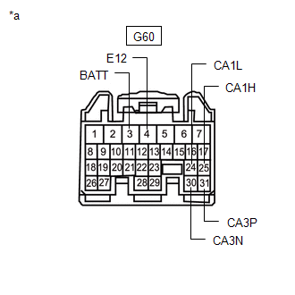
| *a | Front view of wire harness connector (to Hybrid Vehicle Control ECU) |
INVERTER WITH CONVERTER ASSEMBLY
Refer to Terminals of ECU.
Click here
(a) Disconnect the cable from the negative (-) auxiliary battery terminal.
(b) Disconnect the A58 inverter with converter assembly connector.
(c) Measure the resistance according to the value(s) in the table below.
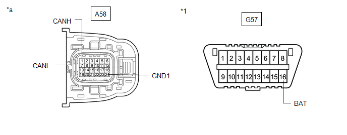
| *1 | DLC3 | - | - |
| *a | Front view of wire harness connector (to Inverter with Converter Assembly) | - | - |
Standard Resistance:
| Terminal No. (Symbol) | Wiring Color | Terminal Description | Condition | Specified Condition |
|---|---|---|---|---|
| A58-1 (CANH) - A58-7 (CANL) | V - W | HIGH-level CAN bus line - LOW-level CAN bus line | Cable disconnected from negative (-) auxiliary battery terminal | 54 to 69 Ω |
| A58-1 (CANH) - A58-24 (GND1) | V - W-B | HIGH-level CAN bus line - Ground | Cable disconnected from negative (-) auxiliary battery terminal | 200 Ω or higher |
| A58-7 (CANL) - A58-24 (GND1) | W - W-B | LOW-level CAN bus line - Ground | Cable disconnected from negative (-) auxiliary battery terminal | 200 Ω or higher |
| A58-1 (CANH) - G57-16 (BAT) | V - R | HIGH-level CAN bus line - Auxiliary battery positive (+) | Cable disconnected from negative (-) auxiliary battery terminal | 6 kΩ or higher |
| A58-7 (CANL) - G57-16 (BAT) | W - R | LOW-level CAN bus line - Auxiliary battery positive (+) | Cable disconnected from negative (-) auxiliary battery terminal | 6 kΩ or higher |
ECM
Refer to Terminals of ECU.
Click here
(a) Disconnect the cable from the negative (-) auxiliary battery terminal.
(b) Disconnect the A26 ECM connector.
(c) Measure the resistance according to the value(s) in the table below.
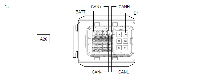
| *a | Front view of wire harness connector (to ECM) | - | - |
Standard Resistance:
Bus 2 Main Lines| Terminal No. (Symbol) | Wiring Color | Terminal Description | Condition | Specified Condition |
|---|---|---|---|---|
| A26-8 (CANH) - A26-18 (CANL) | B - W | HIGH-level CAN bus line - LOW-level CAN bus line | Cable disconnected from negative (-) auxiliary battery terminal | 108 to 132 Ω |
| A26-8 (CANH) - A26-10 (E1) | B - W-B | HIGH-level CAN bus line - Ground | Cable disconnected from negative (-) auxiliary battery terminal | 200 Ω or higher |
| A26-18 (CANL) - A26-10 (E1) | W - W-B | LOW-level CAN bus line - Ground | Cable disconnected from negative (-) auxiliary battery terminal | 200 Ω or higher |
| A26-8 (CANH) - A26-1 (BATT) | B - G | HIGH-level CAN bus line - Auxiliary battery positive (+) | Cable disconnected from negative (-) auxiliary battery terminal | 6 kΩ or higher |
| A26-18 (CANL) - A26-1 (BATT) | W - G | LOW-level CAN bus line - Auxiliary battery positive (+) | Cable disconnected from negative (-) auxiliary battery terminal | 6 kΩ or higher |
| Terminal No. (Symbol) | Wiring Color | Terminal Description | Condition | Specified Condition |
|---|---|---|---|---|
| A26-7 (CAN+) - A26-17 (CAN-) | P - W | HIGH-level CAN bus line - LOW-level CAN bus line | Cable disconnected from negative (-) auxiliary battery terminal | 54 to 69 Ω |
| A26-7 (CAN+) - A26-10 (E1) | P - W-B | HIGH-level CAN bus line - Ground | Cable disconnected from negative (-) auxiliary battery terminal | 200 Ω or higher |
| A26-17 (CAN-) - A26-10 (E1) | W - W-B | LOW-level CAN bus line - Ground | Cable disconnected from negative (-) auxiliary battery terminal | 200 Ω or higher |
| A26-7 (CAN+) - A26-1 (BATT) | P - G | HIGH-level CAN bus line - Auxiliary battery positive (+) | Cable disconnected from negative (-) auxiliary battery terminal | 6 kΩ or higher |
| A26-17 (CAN-) - A26-1 (BATT) | W - G | LOW-level CAN bus line - Auxiliary battery positive (+) | Cable disconnected from negative (-) auxiliary battery terminal | 6 kΩ or higher |
COMBINATION METER ASSEMBLY
Refer to Terminals of ECU.
Click here
(a) Disconnect the cable from the negative (-) auxiliary battery terminal.
(b) Disconnect the G17 combination meter assembly connector.
(c) Measure the resistance according to the value(s) in the table below.
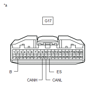
| *a | Front view of wire harness connector (to Combination Meter Assembly) |
Standard Resistance:
| Terminal No. (Symbol) | Wiring Color | Terminal Description | Condition | Specified Condition |
|---|---|---|---|---|
| G17-29 (CANH) - G17-30 (CANL) | B - W | HIGH-level CAN bus line - LOW-level CAN bus line | Cable disconnected from negative (-) auxiliary battery terminal | 108 to 132 Ω |
| G17-29 (CANH) - G17-31 (ES) | B - W-B | HIGH-level CAN bus line - Ground | Cable disconnected from negative (-) auxiliary battery terminal | 200 Ω or higher |
| G17-30 (CANL) - G17-31 (ES) | W - W-B | LOW-level CAN bus line - Ground | Cable disconnected from negative (-) auxiliary battery terminal | 200 Ω or higher |
| G17-29 (CANH) - G17-22 (B) | B - LA-B | HIGH-level CAN bus line - Auxiliary battery positive (+) | Cable disconnected from negative (-) auxiliary battery terminal | 6 kΩ or higher |
| G17-30 (CANL) - G17-22 (B) | W - LA-B | LOW-level CAN bus line - Auxiliary battery positive (+) | Cable disconnected from negative (-) auxiliary battery terminal | 6 kΩ or higher |
BRAKE BOOSTER WITH MASTER CYLINDER ASSEMBLY
Refer to Terminals of ECU.
Click here
(a) Disconnect the cable from the negative (-) auxiliary battery terminal.
(b) Disconnect the A45 brake booster with master cylinder assembly connector.
(c) Measure the resistance according to the value(s) in the table below.
Standard Resistance:
Bus 2 Branch Lines| Terminal No. (Symbol) | Wiring Color | Terminal Description | Condition | Specified Condition |
|---|---|---|---|---|
| A45-30 (CA2H) - A45-29 (CA2L) | LG - W | HIGH-level CAN bus line - LOW-level CAN bus line | Cable disconnected from negative (-) auxiliary battery terminal | 54 to 69 Ω |
| A45-30 (CA2H) - A45-26 (GND1) | LG - LA | HIGH-level CAN bus line - Ground | Cable disconnected from negative (-) auxiliary battery terminal | 200 Ω or higher |
| A45-29 (CA2L) - A45-26 (GND1) | W - LA | LOW-level CAN bus line - Ground | Cable disconnected from negative (-) auxiliary battery terminal | 200 Ω or higher |
| A45-30 (CA2H) - A45-52 (BS) | LG - LG | HIGH-level CAN bus line - Auxiliary battery positive (+) | Cable disconnected from negative (-) auxiliary battery terminal | 6 kΩ or higher |
| A45-29 (CA2L) - A45-52 (BS) | W - LG | LOW-level CAN bus line - Auxiliary battery positive (+) | Cable disconnected from negative (-) auxiliary battery terminal | 6 kΩ or higher |
| Terminal No. (Symbol) | Wiring Color | Terminal Description | Condition | Specified Condition |
|---|---|---|---|---|
| A45-43 (CA1H) - A45-42 (CA1L) | Y - W | HIGH-level CAN bus line - LOW-level CAN bus line | Cable disconnected from negative (-) auxiliary battery terminal | 54 to 69 Ω |
| A45-43 (CA1H) - A45-26 (GND1) | Y - LA | HIGH-level CAN bus line - Ground | Cable disconnected from negative (-) auxiliary battery terminal | 200 Ω or higher |
| A45-42 (CA1L) - A45-26 (GND1) | W - LA | LOW-level CAN bus line - Ground | Cable disconnected from negative (-) auxiliary battery terminal | 200 Ω or higher |
| A45-43 (CA1H) - A45-52 (BS) | Y - LG | HIGH-level CAN bus line - Auxiliary battery positive (+) | Cable disconnected from negative (-) auxiliary battery terminal | 6 kΩ or higher |
| A45-42 (CA1L) - A45-52 (BS) | W - LG | LOW-level CAN bus line - Auxiliary battery positive (+) | Cable disconnected from negative (-) auxiliary battery terminal | 6 kΩ or higher |
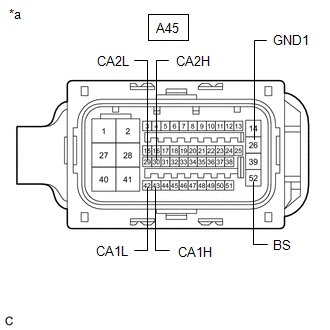
| *a | Front view of wire harness connector (to Brake Booster with Master Cylinder Assembly) |
MAIN BODY ECU (MULTIPLEX NETWORK BODY ECU)
Refer to Terminals of ECU.
Click here
(a) Disconnect the cable from the negative (-) auxiliary battery terminal.
(b) Disconnect the G37 main body ECU (multiplex network body ECU) connector.
(c) Measure the resistance according to the value(s) in the table below.
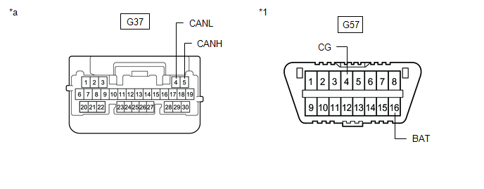
| *1 | DLC3 | - | - |
| *a | Front view of wire harness connector (to Main Body ECU (Multiplex Network Body ECU)) | - | - |
Standard Resistance:
| Terminal No. (Symbol) | Wiring Color | Terminal Description | Condition | Specified Condition |
|---|---|---|---|---|
| G37-5 (CANH) - G37-4 (CANL) | BE - W | HIGH-level CAN bus line - LOW-level CAN bus line | Cable disconnected from negative (-) auxiliary battery terminal | 54 to 69 Ω |
| G37-5 (CANH) - G57-4 (CG) | BE - W-B | HIGH-level CAN bus line - Ground | Cable disconnected from negative (-) auxiliary battery terminal | 200 Ω or higher |
| G37-4 (CANL) - G57-4 (CG) | W - W-B | LOW-level CAN bus line - Ground | Cable disconnected from negative (-) auxiliary battery terminal | 200 Ω or higher |
| G37-5 (CANH) - G57-16 (BAT) | BE - R | HIGH-level CAN bus line - Auxiliary battery positive (+) | Cable disconnected from negative (-) auxiliary battery terminal | 6 kΩ or higher |
| G37-4 (CANL) - G57-16 (BAT) | W - R | LOW-level CAN bus line - Auxiliary battery positive (+) | Cable disconnected from negative (-) auxiliary battery terminal | 6 kΩ or higher |
CERTIFICATION ECU (SMART KEY ECU ASSEMBLY)
Refer to Terminals of ECU.
Click here
(a) Disconnect the cable from the negative (-) auxiliary battery terminal.
(b) Disconnect the G47 certification ECU (smart key ECU assembly) connector.
(c) Measure the resistance according to the value(s) in the table below.
Standard Resistance:
| Terminal No. (Symbol) | Wiring Color | Terminal Description | Condition | Specified Condition |
|---|---|---|---|---|
| G47-1 (CANH) - G47-2 (CANL) | G - W | HIGH-level CAN bus line - LOW-level CAN bus line | Cable disconnected from negative (-) auxiliary battery terminal | 54 to 69 Ω |
| G47-1 (CANH) - G47-18 (E) | G - W-B | HIGH-level CAN bus line - Ground | Cable disconnected from negative (-) auxiliary battery terminal | 200 Ω or higher |
| G47-2 (CANL) - G47-18 (E) | W - W-B | LOW-level CAN bus line - Ground | Cable disconnected from negative (-) auxiliary battery terminal | 200 Ω or higher |
| G47-1 (CANH) - G47-4 (+B) | G - W | HIGH-level CAN bus line - Auxiliary battery positive (+) | Cable disconnected from negative (-) auxiliary battery terminal | 6 kΩ or higher |
| G47-2 (CANL) - G47-4 (+B) | W - W | LOW-level CAN bus line - Auxiliary battery positive (+) | Cable disconnected from negative (-) auxiliary battery terminal | 6 kΩ or higher |
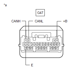
| *a | Front view of wire harness connector (to Certification ECU (Smart Key ECU Assembly)) |
RACK AND PINION POWER STEERING GEAR ASSEMBLY
Refer to Terminals of ECU.
Click here
(a) Disconnect the cable from the negative (-) auxiliary battery terminal.
(b) Disconnect the C37 rack and pinion power steering gear assembly connector.
(c) Measure the resistance according to the value(s) in the table below.
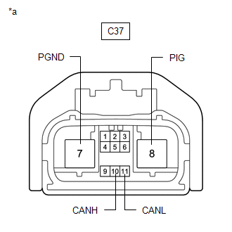
| *a | Front view of wire harness connector (to Rack and Pinion Power Steering Gear Assembly) |
Standard Resistance:
| Terminal No. (Symbol) | Wiring Color | Terminal Description | Condition | Specified Condition |
|---|---|---|---|---|
| C37-10 (CANH) - C37-11 (CANL) | G - W | HIGH-level CAN bus line - LOW-level CAN bus line | Cable disconnected from negative (-) auxiliary battery terminal | 54 to 69 Ω |
| C37-10 (CANH) - C37-7 (PGND) | G - B | HIGH-level CAN bus line - Ground | Cable disconnected from negative (-) auxiliary battery terminal | 200 Ω or higher |
| C37-11 (CANL) - C37-7 (PGND) | W - B | LOW-level CAN bus line - Ground | Cable disconnected from negative (-) auxiliary battery terminal | 200 Ω or higher |
| C37-10 (CANH) - C37-8 (PIG) | G - W | HIGH-level CAN bus line - Auxiliary battery positive (+) | Cable disconnected from negative (-) auxiliary battery terminal | 6 kΩ or higher |
| C37-11 (CANL) - C37-8 (PIG) | W - W | LOW-level CAN bus line - Auxiliary battery positive (+) | Cable disconnected from negative (-) auxiliary battery terminal | 6 kΩ or higher |
AIRBAG ECU ASSEMBLY
Refer to Terminals of ECU.
Click here
(a) Disconnect the cable from the negative (-) auxiliary battery terminal.
(b) Disconnect the G64 airbag ECU assembly connector.
(c) Measure the resistance according to the value(s) in the table below.
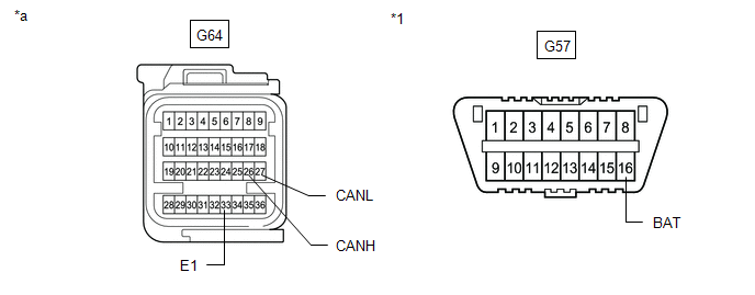
| *1 | DLC3 | - | - |
| *a | Front view of wire harness connector (to Airbag ECU Assembly) | - | - |
Standard Resistance:
| Terminal No. (Symbol) | Wiring Color | Terminal Description | Condition | Specified Condition |
|---|---|---|---|---|
| G64-26 (CANH) - G64-27 (CANL) | Y - W | HIGH-level CAN bus line - LOW-level CAN bus line | Cable disconnected from negative (-) auxiliary battery terminal | 108 to 132 Ω |
| G64-26 (CANH) - G64-33 (E1) | Y - W-B | HIGH-level CAN bus line - Ground | Cable disconnected from negative (-) auxiliary battery terminal | 200 Ω or higher |
| G64-27 (CANL) - G64-33 (E1) | W - W-B | LOW-level CAN bus line - Ground | Cable disconnected from negative (-) auxiliary battery terminal | 200 Ω or higher |
| G64-26 (CANH) - G57-16 (BAT) | Y - R | HIGH-level CAN bus line - Auxiliary battery positive (+) | Cable disconnected from negative (-) auxiliary battery terminal | 6 kΩ or higher |
| G64-27 (CANL) - G57-16 (BAT) | W - R | LOW-level CAN bus line - Auxiliary battery positive (+) | Cable disconnected from negative (-) auxiliary battery terminal | 6 kΩ or higher |
AIR CONDITIONING AMPLIFIER ASSEMBLY
Refer to Terminals of ECU.
Click here
(a) Disconnect the cable from the negative (-) auxiliary battery terminal.
(b) Disconnect the G39 air conditioning amplifier assembly connector.
(c) Measure the resistance according to the value(s) in the table below.
Standard Resistance:
| Terminal No. (Symbol) | Wiring Color | Terminal Description | Condition | Specified Condition |
|---|---|---|---|---|
| G39-11 (CANH) - G39-12 (CANL) | SB - W | HIGH-level CAN bus line - LOW-level CAN bus line | Cable disconnected from negative (-) auxiliary battery terminal | 54 to 69 Ω |
| G39-11 (CANH) - G39-4 (GND) | SB - W-B | HIGH-level CAN bus line - Ground | Cable disconnected from negative (-) auxiliary battery terminal | 200 Ω or higher |
| G39-12 (CANL) - G39-4 (GND) | W - W-B | LOW-level CAN bus line - Ground | Cable disconnected from negative (-) auxiliary battery terminal | 200 Ω or higher |
| G39-11 (CANH) - G39-1 (B) | SB - B | HIGH-level CAN bus line - Auxiliary battery positive (+) | Cable disconnected from negative (-) auxiliary battery terminal | 6 kΩ or higher |
| G39-12 (CANL) - G39-1 (B) | W - B | LOW-level CAN bus line - Auxiliary battery positive (+) | Cable disconnected from negative (-) auxiliary battery terminal | 6 kΩ or higher |
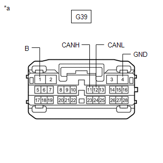
| *a | Front view of wire harness connector (to Air Conditioning Amplifier Assembly) |
RADIO RECEIVER ASSEMBLY (for Navigation Receiver Type)
Refer to Terminals of ECU.
Click here
(a) Disconnect the cable from the negative (-) auxiliary battery terminal.
(b) Disconnect the G3 radio receiver assembly connector.
(c) Measure the resistance according to the value(s) in the table below.

| *1 | DLC3 | - | - |
| *a | Front view of wire harness connector (to Radio Receiver Assembly) | - | - |
Standard Resistance:
| Terminal No. (Symbol) | Wiring Color | Terminal Description | Condition | Specified Condition |
|---|---|---|---|---|
| G3-13 (CANH) - G3-14 (CANL) | B - W | HIGH-level CAN bus line - LOW-level CAN bus line | Cable disconnected from negative (-) auxiliary battery terminal | 54 to 69 Ω |
| G3-13 (CANH) - G57-4 (CG) | B - W-B | HIGH-level CAN bus line - Ground | Cable disconnected from negative (-) auxiliary battery terminal | 200 Ω or higher |
| G3-14 (CANL) - G57-4 (CG) | W - W-B | LOW-level CAN bus line - Ground | Cable disconnected from negative (-) auxiliary battery terminal | 200 Ω or higher |
| G3-13 (CANH) - G57-16 (BAT) | B - R | HIGH-level CAN bus line - Auxiliary battery positive (+) | Cable disconnected from negative (-) auxiliary battery terminal | 6 kΩ or higher |
| G3-14 (CANL) - G57-16 (BAT) | W - R | LOW-level CAN bus line - Auxiliary battery positive (+) | Cable disconnected from negative (-) auxiliary battery terminal | 6 kΩ or higher |
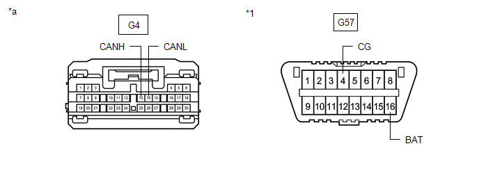
RADIO RECEIVER ASSEMBLY (for Radio and Display Type)
Refer to Terminals of ECU.
Click here
(a) Disconnect the cable from the negative (-) auxiliary battery terminal.
(b) Disconnect the G4 radio receiver assembly connector.
(c) Measure the resistance according to the value(s) in the table below.
| *1 | DLC3 | - | - |
| *a | Front view of wire harness connector (to Radio Receiver Assembly) | - | - |
Standard Resistance:
| Terminal No. (Symbol) | Wiring Color | Terminal Description | Condition | Specified Condition |
|---|---|---|---|---|
| G4-13 (CANH) - G4-14 (CANL) | B - W | HIGH-level CAN bus line - LOW-level CAN bus line | Cable disconnected from negative (-) auxiliary battery terminal | 54 to 69 Ω |
| G4-13 (CANH) - G57-4 (CG) | B - W-B | HIGH-level CAN bus line - Ground | Cable disconnected from negative (-) auxiliary battery terminal | 200 Ω or higher |
| G4-14 (CANL) - G57-4 (CG) | W - W-B | LOW-level CAN bus line - Ground | Cable disconnected from negative (-) auxiliary battery terminal | 200 Ω or higher |
| G4-13 (CANH) - G57-16 (BAT) | B - R | HIGH-level CAN bus line - Auxiliary battery positive (+) | Cable disconnected from negative (-) auxiliary battery terminal | 6 kΩ or higher |
| G4-14 (CANL) - G57-16 (BAT) | W - R | LOW-level CAN bus line - Auxiliary battery positive (+) | Cable disconnected from negative (-) auxiliary battery terminal | 6 kΩ or higher |
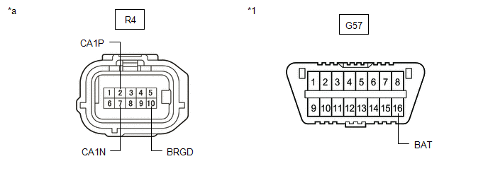
BLIND SPOT MONITOR SENSOR RH (w/ Blind Spot Monitor System)
Refer to Terminals of ECU.
Click here
(a) Disconnect the cable from the negative (-) auxiliary battery terminal.
(b) Disconnect the R4 blind spot monitor sensor RH connector.
(c) Measure the resistance according to the value(s) in the table below.
| *1 | DLC3 | - | - |
| *a | Front view of wire harness connector (to Blind Spot Monitor Sensor RH) | - | - |
Standard Resistance:
| Terminal No. (Symbol) | Wiring Color | Terminal Description | Condition | Specified Condition |
|---|---|---|---|---|
| R4-2 (CA1P) - R4-7 (CA1N) | V - W | HIGH-level CAN bus line - LOW-level CAN bus line | Cable disconnected from negative (-) auxiliary battery terminal | 54 to 69 Ω |
| R4-2 (CA1P) - R4-10 (BRGD) | V - W-B | HIGH-level CAN bus line - Ground | Cable disconnected from negative (-) auxiliary battery terminal | 200 Ω or higher |
| R4-7 (CA1N) - R4-10 (BRGD) | W - W-B | LOW-level CAN bus line - Ground | Cable disconnected from negative (-) auxiliary battery terminal | 200 Ω or higher |
| R4-2 (CA1P) - G57-16 (BAT) | V - R | HIGH-level CAN bus line - Auxiliary battery positive (+) | Cable disconnected from negative (-) auxiliary battery terminal | 6 kΩ or higher |
| R4-7 (CA1N) - G57-16 (BAT) | W - R | LOW-level CAN bus line - Auxiliary battery positive (+) | Cable disconnected from negative (-) auxiliary battery terminal | 6 kΩ or higher |
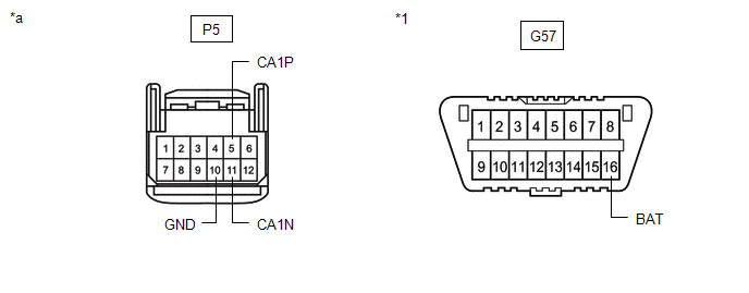
FORWARD RECOGNITION CAMERA
Refer to Terminals of ECU.
Click here
(a) Disconnect the cable from the negative (-) auxiliary battery terminal.
(b) Disconnect the P5 forward recognition camera connector.
(c) Measure the resistance according to the value(s) in the table below.
| *1 | DLC3 | - | - |
| *a | Front view of wire harness connector (to Forward Recognition Camera) | - | - |
Standard Resistance:
| Terminal No. (Symbol) | Wiring Color | Terminal Description | Condition | Specified Condition |
|---|---|---|---|---|
| P5-5 (CA1P) - P5-11 (CA1N) | L - W | HIGH-level CAN bus line - LOW-level CAN bus line | Cable disconnected from negative (-) auxiliary battery terminal | 54 to 69 Ω |
| P5-5 (CA1P) - P5-10 (GND) | L - LA | HIGH-level CAN bus line - Ground | Cable disconnected from negative (-) auxiliary battery terminal | 200 Ω or higher |
| P5-11 (CA1N) - P5-10 (GND) | W - LA | LOW-level CAN bus line - Ground | Cable disconnected from negative (-) auxiliary battery terminal | 200 Ω or higher |
| P5-5 (CA1P) - G57-16 (BAT) | L - R | HIGH-level CAN bus line - Auxiliary battery positive (+) | Cable disconnected from negative (-) auxiliary battery terminal | 6 kΩ or higher |
| P5-11 (CA1N) - G57-16 (BAT) | W - R | LOW-level CAN bus line - Auxiliary battery positive (+) | Cable disconnected from negative (-) auxiliary battery terminal | 6 kΩ or higher |
MILLIMETER WAVE RADAR SENSOR ASSEMBLY
Refer to Terminals of ECU.
Click here
(a) Disconnect the cable from the negative (-) auxiliary battery terminal.
(b) Disconnect the A37 millimeter wave radar sensor assembly connector.
(c) Measure the resistance according to the value(s) in the table below.
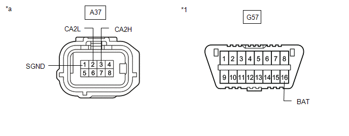
| *1 | DLC3 | - | - |
| *a | Front view of wire harness connector (to Millimeter Wave Radar Sensor Assembly) | - | - |
Standard Resistance:
| Terminal No. (Symbol) | Wiring Color | Terminal Description | Condition | Specified Condition |
|---|---|---|---|---|
| A37-3 (CA2H) - A37-2 (CA2L) | R - W | HIGH-level CAN bus line - LOW-level CAN bus line | Cable disconnected from negative (-) auxiliary battery terminal | 54 to 69 Ω |
| A37-3 (CA2H) - A37-1 (SGND) | R - W-B | HIGH-level CAN bus line - Ground | Cable disconnected from negative (-) auxiliary battery terminal | 200 Ω or higher |
| A37-2 (CA2L) - A37-1 (SGND) | W - W-B | LOW-level CAN bus line - Ground | Cable disconnected from negative (-) auxiliary battery terminal | 200 Ω or higher |
| A37-3 (CA2H) - G57-16 (BAT) | R - R | HIGH-level CAN bus line - Auxiliary battery positive (+) | Cable disconnected from negative (-) auxiliary battery terminal | 6 kΩ or higher |
| A37-2 (CA2L) - G57-16 (BAT) | W - R | LOW-level CAN bus line - Auxiliary battery positive (+) | Cable disconnected from negative (-) auxiliary battery terminal | 6 kΩ or higher |
OCCUPANT DETECTION ECU
Refer to Terminals of ECU.
Click here
(a) Disconnect the cable from the negative (-) auxiliary battery terminal.
(b) Disconnect the U28 occupant detection ECU connector.
(c) Measure the resistance according to the value(s) in the table below.
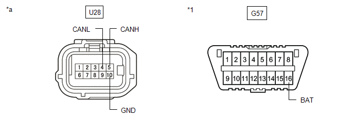
| *1 | DLC3 | - | - |
| *a | Front view of wire harness connector (to Occupant Detection ECU) | - | - |
Standard Resistance:
| Terminal No. (Symbol) | Wiring Color | Terminal Description | Condition | Specified Condition |
|---|---|---|---|---|
| U28-5 (CANH) - U28-4 (CANL) | R - SB*1 L - W*2 | HIGH-level CAN bus line - LOW-level CAN bus line | Cable disconnected from negative (-) auxiliary battery terminal | 54 to 69 Ω |
| U28-5 (CANH) - U28-10 (GND) | R - W-B*1 L - W-B*2 | HIGH-level CAN bus line - Ground | Cable disconnected from negative (-) auxiliary battery terminal | 200 Ω or higher |
| U28-4 (CANL) - U28-10 (GND) | SB - W-B*1 W - W-B*2 | LOW-level CAN bus line - Ground | Cable disconnected from negative (-) auxiliary battery terminal | 200 Ω or higher |
| U28-5 (CANH) - G57-16 (BAT) | R - R*1 L - R*2 | HIGH-level CAN bus line - Auxiliary battery positive (+) | Cable disconnected from negative (-) auxiliary battery terminal | 6 kΩ or higher |
| U28-4 (CANL) - G57-16 (BAT) | SB - R*1 W - R*2 | LOW-level CAN bus line - Auxiliary battery positive (+) | Cable disconnected from negative (-) auxiliary battery terminal | 6 kΩ or higher |
- *1: for TMC Made
- *2: for TMMK Made
OPTION CONNECTOR (BUS BUFFER ECU) (w/ CAN Compatible Optional Devices)
(a) Disconnect the cable from the negative (-) auxiliary battery terminal.
(b) Disconnect the G80 option connector (bus buffer ECU).
HINT:
Disconnect any CAN compatible optional devices from the option connector.
(c) Measure the resistance according to the value(s) in the table below.
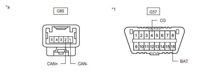
| *1 | DLC3 | - | - |
| *a | Front view of wire harness connector (to Option Connector (Bus Buffer ECU)) | - | - |
Standard Resistance:
| Terminal No. (Symbol) | Wiring Color | Terminal Description | Condition | Specified Condition |
|---|---|---|---|---|
| G80-2 (CAN+) - G80-1 (CAN-) | L - W | HIGH-level CAN bus line - LOW-level CAN bus line | Cable disconnected from negative (-) auxiliary battery terminal | 54 to 69 Ω |
| G80-2 (CAN+) - G57-4 (CG) | L - W-B | HIGH-level CAN bus line - Ground | Cable disconnected from negative (-) auxiliary battery terminal | 200 Ω or higher |
| G80-1 (CAN-) - G57-4 (CG) | W - W-B | LOW-level CAN bus line - Ground | Cable disconnected from negative (-) auxiliary battery terminal | 200 Ω or higher |
| G80-2 (CAN+) - G57-16 (BAT) | L - R | HIGH-level CAN bus line - Auxiliary battery positive (+) | Cable disconnected from negative (-) auxiliary battery terminal | 6 kΩ or higher |
| G80-1 (CAN-) - G57-16 (BAT) | W - R | LOW-level CAN bus line - Auxiliary battery positive (+) | Cable disconnected from negative (-) auxiliary battery terminal | 6 kΩ or higher |
DCM (TELEMATICS TRANSCEIVER) (w/ Telematics Transceiver)
Refer to Terminals of ECU.
Click here
(a) Disconnect the cable from the negative (-) auxiliary battery terminal.
(b) Disconnect the G128 DCM (telematics transceiver) connector.
(c) Measure the resistance according to the value(s) in the table below.
Standard Resistance:
| Terminal No. (Symbol) | Wiring Color | Terminal Description | Condition | Specified Condition |
|---|---|---|---|---|
| G128-25 (CANP) - G128-26 (CANN) | R - W | HIGH-level CAN bus line - LOW-level CAN bus line | Cable disconnected from negative (-) auxiliary battery terminal | 54 to 69 Ω |
| G128-25 (CANP) - G128-20 (E) | R - W-B | HIGH-level CAN bus line - Ground | Cable disconnected from negative (-) auxiliary battery terminal | 200 Ω or higher |
| G128-26 (CANN) - G128-20 (E) | W - W-B | LOW-level CAN bus line - Ground | Cable disconnected from negative (-) auxiliary battery terminal | 200 Ω or higher |
| G128-25 (CANP) - G128-1 (+B) | R - GR | HIGH-level CAN bus line - Auxiliary battery positive (+) | Cable disconnected from negative (-) auxiliary battery terminal | 6 kΩ or higher |
| G128-26 (CANN) - G128-1 (+B) | W - GR | LOW-level CAN bus line - Auxiliary battery positive (+) | Cable disconnected from negative (-) auxiliary battery terminal | 6 kΩ or higher |
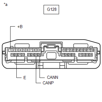
| *a | Front view of wire harness connector (to DCM (Telematics Transceiver)) |
REAR TELEVISION CAMERA ASSEMBLY (w/ Panoramic View Monitor System)
Refer to Terminals of ECU.
Click here
(a) Disconnect the cable from the negative (-) auxiliary battery terminal.
(b) Disconnect the T2 rear television camera assembly connector.
(c) Measure the resistance according to the value(s) in the table below.
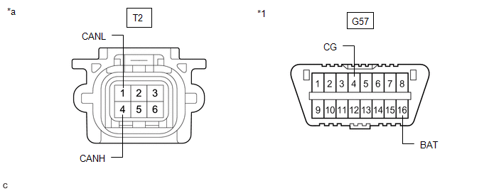
| *1 | DLC3 | - | - |
| *a | Front view of wire harness connector (to Rear Television Camera Assembly) | - | - |
Standard Resistance:
| Terminal No. (Symbol) | Wiring Color | Terminal Description | Condition | Specified Condition |
|---|---|---|---|---|
| T2-4 (CANH) - T2-1 (CANL) | R - W | HIGH-level CAN bus line - LOW-level CAN bus line | Cable disconnected from negative (-) auxiliary battery terminal | 54 to 69 Ω |
| T2-4 (CANH) - G57-4 (CG) | R - W-B | HIGH-level CAN bus line - Ground | Cable disconnected from negative (-) auxiliary battery terminal | 200 Ω or higher |
| T2-1 (CANL) - G57-4 (CG) | W - W-B | LOW-level CAN bus line - Ground | Cable disconnected from negative (-) auxiliary battery terminal | 200 Ω or higher |
| T2-4 (CANH) - G57-16 (BAT) | R - R | HIGH-level CAN bus line - Auxiliary battery positive (+) | Cable disconnected from negative (-) auxiliary battery terminal | 6 kΩ or higher |
| T2-1 (CANL) - G57-16 (BAT) | W - R | LOW-level CAN bus line - Auxiliary battery positive (+) | Cable disconnected from negative (-) auxiliary battery terminal | 6 kΩ or higher |
REAR TELEVISION CAMERA ASSEMBLY (w/o Panoramic View Monitor System)
Refer to Terminals of ECU.
Click here
(a) Disconnect the cable from the negative (-) auxiliary battery terminal.
(b) Disconnect the T1 rear television camera assembly connector.
(c) Measure the resistance according to the value(s) in the table below.
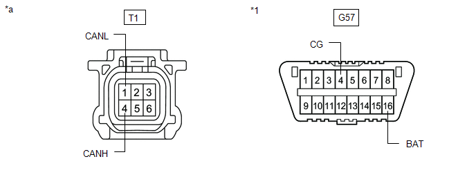
| *1 | DLC3 | - | - |
| *a | Front view of wire harness connector (to Rear Television Camera Assembly) | - | - |
Standard Resistance:
| Terminal No. (Symbol) | Wiring Color | Terminal Description | Condition | Specified Condition |
|---|---|---|---|---|
| T1-4 (CANH) - T1-1 (CANL) | R - W | HIGH-level CAN bus line - LOW-level CAN bus line | Cable disconnected from negative (-) auxiliary battery terminal | 54 to 69 Ω |
| T1-4 (CANH) - G57-4 (CG) | R - W-B | HIGH-level CAN bus line - Ground | Cable disconnected from negative (-) auxiliary battery terminal | 200 Ω or higher |
| T1-1 (CANL) - G57-4 (CG) | W - W-B | LOW-level CAN bus line - Ground | Cable disconnected from negative (-) auxiliary battery terminal | 200 Ω or higher |
| T1-4 (CANH) - G57-16 (BAT) | R - R | HIGH-level CAN bus line - Auxiliary battery positive (+) | Cable disconnected from negative (-) auxiliary battery terminal | 6 kΩ or higher |
| T1-1 (CANL) - G57-16 (BAT) | W - R | LOW-level CAN bus line - Auxiliary battery positive (+) | Cable disconnected from negative (-) auxiliary battery terminal | 6 kΩ or higher |
TIRE PRESSURE WARNING ECU AND RECEIVER
Refer to Terminals of ECU.
Click here
(a) Disconnect the cable from the negative (-) auxiliary battery terminal.
(b) Disconnect the N8 tire pressure warning ECU and receiver connector.
(c) Measure the resistance according to the value(s) in the table below.
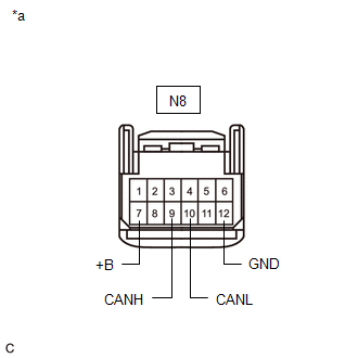
| *a | Front view of wire harness connector (to Tire Pressure Warning ECU and Receiver) |
Standard Resistance:
| Terminal No. (Symbol) | Wiring Color | Terminal Description | Condition | Specified Condition |
|---|---|---|---|---|
| N8-9 (CANH) - N8-10 (CANL) | L - W | HIGH-level CAN bus line - LOW-level CAN bus line | Cable disconnected from negative (-) auxiliary battery terminal | 54 to 69 Ω |
| N8-9 (CANH) - N8-12 (GND) | L - BR | HIGH-level CAN bus line - Ground | Cable disconnected from negative (-) auxiliary battery terminal | 200 Ω or higher |
| N8-10 (CANL) - N8-12 (GND) | W - BR | LOW-level CAN bus line - Ground | Cable disconnected from negative (-) auxiliary battery terminal | 200 Ω or higher |
| N8-9 (CANH) - N8-7 (+B) | L - R | HIGH-level CAN bus line - Auxiliary battery positive (+) | Cable disconnected from negative (-) auxiliary battery terminal | 6 kΩ or higher |
| N8-10 (CANL) - N8-7 (+B) | W - R | LOW-level CAN bus line - Auxiliary battery positive (+) | Cable disconnected from negative (-) auxiliary battery terminal | 6 kΩ or higher |
BRAKE ACTUATOR ASSEMBLY
Refer to Terminals of ECU.
Click here
(a) Disconnect the cable from the negative (-) auxiliary battery terminal.
(b) Disconnect the A54 brake actuator assembly connector.
(c) Measure the resistance according to the value(s) in the table below.
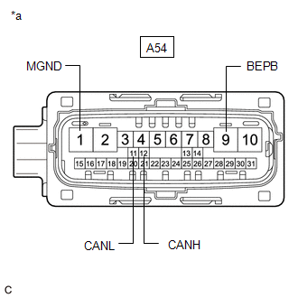
| *a | Front view of wire harness connector (to Brake Actuator Assembly) |
Standard Resistance:
| Terminal No. (Symbol) | Wiring Color | Terminal Description | Condition | Specified Condition |
|---|---|---|---|---|
| A54-12 (CANH) - A54-11 (CANL) | B - W | HIGH-level CAN bus line - LOW-level CAN bus line | Cable disconnected from negative (-) auxiliary battery terminal | 54 to 69 Ω |
| A54-12 (CANH) - A54-1 (MGND) | B - W-B | HIGH-level CAN bus line - Ground | Cable disconnected from negative (-) auxiliary battery terminal | 200 Ω or higher |
| A54-11 (CANL) - A54-1 (MGND) | W - W-B | LOW-level CAN bus line - Ground | Cable disconnected from negative (-) auxiliary battery terminal | 200 Ω or higher |
| A54-12 (CANH) - A54-9 (BEPB) | B - R | HIGH-level CAN bus line - Auxiliary battery positive (+) | Cable disconnected from negative (-) auxiliary battery terminal | 6 kΩ or higher |
| A54-11 (CANL) - A54-9 (BEPB) | W - R | LOW-level CAN bus line - Auxiliary battery positive (+) | Cable disconnected from negative (-) auxiliary battery terminal | 6 kΩ or higher |
METER MIRROR SUB-ASSEMBLY (w/ Headup Display System)
Refer to Terminals of ECU.
Click here
(a) Disconnect the cable from the negative (-) auxiliary battery terminal.
(b) Disconnect the G27 meter mirror sub-assembly connector.
(c) Measure the resistance according to the value(s) in the table below.
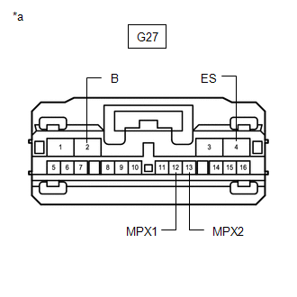
| *a | Front view of wire harness connector (to Meter Mirror Sub-assembly) |
Standard Resistance:
| Terminal No. (Symbol) | Wiring Color | Terminal Description | Condition | Specified Condition |
|---|---|---|---|---|
| G27-12 (MPX1) - G27-13 (MPX2) | LG - W | HIGH-level CAN bus line - LOW-level CAN bus line | Cable disconnected from negative (-) auxiliary battery terminal | 54 to 69 Ω |
| G27-12 (MPX1) - G27-4 (ES) | LG - W-B | HIGH-level CAN bus line - Ground | Cable disconnected from negative (-) auxiliary battery terminal | 200 Ω or higher |
| G27-13 (MPX2) - G27-4 (ES) | W - W-B | LOW-level CAN bus line - Ground | Cable disconnected from negative (-) auxiliary battery terminal | 200 Ω or higher |
| G27-12 (MPX1) - G27-2 (B) | LG - LA-R | HIGH-level CAN bus line - Auxiliary battery positive (+) | Cable disconnected from negative (-) auxiliary battery terminal | 6 kΩ or higher |
| G27-13 (MPX2) - G27-2 (B) | W - LA-R | LOW-level CAN bus line - Auxiliary battery positive (+) | Cable disconnected from negative (-) auxiliary battery terminal | 6 kΩ or higher |
HEADLIGHT ECU SUB-ASSEMBLY LH
Refer to Terminals of ECU.
Click here
(a) Disconnect the cable from the negative (-) auxiliary battery terminal.
(b) Disconnect the A78 headlight ECU sub-assembly LH connector.
(c) Measure the resistance according to the value(s) in the table below.
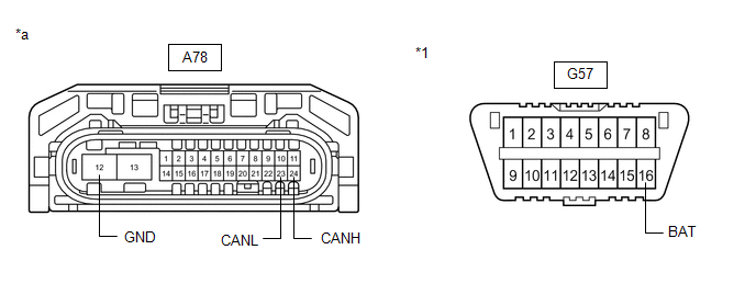
| *1 | DLC3 | - | - |
| *a | Front view of wire harness connector (to Headlight ECU Sub-assembly LH) | - | - |
Standard Resistance:
| Terminal No. (Symbol) | Wiring Color | Terminal Description | Condition | Specified Condition |
|---|---|---|---|---|
| A78-24(CANH) - A78-23(CANL) | R - W | HIGH-level CAN bus line - LOW-level CAN bus line | Cable disconnected from negative (-) auxiliary battery terminal | 54 to 69 Ω |
| A78-24(CANH)) - A78-12 (GND) | R - W-B | HIGH-level CAN bus line - Ground | Cable disconnected from negative (-) auxiliary battery terminal | 200 Ω or higher |
| A78-23(CANL) - A78-12 (GND) | W - W-B | LOW-level CAN bus line - Ground | Cable disconnected from negative (-) auxiliary battery terminal | 200 Ω or higher |
| A78-24(CANH) - G57-16 (BAT) | R - R | HIGH-level CAN bus line - Auxiliary battery positive (+) | Cable disconnected from negative (-) auxiliary battery terminal | 6 kΩ or higher |
| A78-23(CANL) - G57-16 (BAT) | W - R | LOW-level CAN bus line - Auxiliary battery positive (+) | Cable disconnected from negative (-) auxiliary battery terminal | 6 kΩ or higher |
HEADLIGHT ECU SUB-ASSEMBLY RH
Refer to Terminals of ECU.
Click here
(a) Disconnect the cable from the negative (-) auxiliary battery terminal.
(b) Disconnect the A79 headlight ECU sub-assembly RH connector.
(c) Measure the resistance according to the value(s) in the table below.

| *1 | DLC3 | - | - |
| *a | Front view of wire harness connector (to Headlight ECU Sub-assembly RH) | - | - |
Standard Resistance:
| Terminal No. (Symbol) | Wiring Color | Terminal Description | Condition | Specified Condition |
|---|---|---|---|---|
| A79-24(CANH) - A79-23(CANL) | L - W | HIGH-level CAN bus line - LOW-level CAN bus line | Cable disconnected from negative (-) auxiliary battery terminal | 54 to 69 Ω |
| A79-24(CANH)) - A79-12 (GND) | L - W-B | HIGH-level CAN bus line - Ground | Cable disconnected from negative (-) auxiliary battery terminal | 200 Ω or higher |
| A79-23(CANL) - A79-12 (GND) | W - W-B | LOW-level CAN bus line - Ground | Cable disconnected from negative (-) auxiliary battery terminal | 200 Ω or higher |
| A79-24(CANH) - G57-16 (BAT) | L - R | HIGH-level CAN bus line - Auxiliary battery positive (+) | Cable disconnected from negative (-) auxiliary battery terminal | 6 kΩ or higher |
| A79-23(CANL) - G57-16 (BAT) | W - R | LOW-level CAN bus line - Auxiliary battery positive (+) | Cable disconnected from negative (-) auxiliary battery terminal | 6 kΩ or higher |
SWING GRILLE ACTUATOR ASSEMBLY
Refer to Terminals of ECU.
Click here
(a) Disconnect the cable from the negative (-) auxiliary battery terminal.
(b) Disconnect the z23 swing grille actuator assembly connector.
(c) Measure the resistance according to the value(s) in the table below.
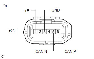
| *a | Front view of wire harness connector (to Swing Grille Actuator Assembly) |
Standard Resistance:
| Terminal No. (Symbol) | Wiring Color | Terminal Description | Condition | Specified Condition |
|---|---|---|---|---|
| z23-6(CAN-P) - z23-5(CAN-N) | # | HIGH-level CAN bus line - LOW-level CAN bus line | Cable disconnected from negative (-) auxiliary battery terminal | 54 to 69 Ω |
| z23-6(CAN-P) - z23-3 (GND) | # | HIGH-level CAN bus line - Ground | Cable disconnected from negative (-) auxiliary battery terminal | 200 Ω or higher |
| z23-5(CAN-N) - z23-3 (GND) | # | LOW-level CAN bus line - Ground | Cable disconnected from negative (-) auxiliary battery terminal | 200 Ω or higher |
| z23-6(CAN-P) - z23-1 (+B) | # | HIGH-level CAN bus line - Auxiliary battery positive (+) | Cable disconnected from negative (-) auxiliary battery terminal | 6 kΩ or higher |
| z23-5(CAN-N) - z23-1 (+B) | # | LOW-level CAN bus line - Auxiliary battery positive (+) | Cable disconnected from negative (-) auxiliary battery terminal | 6 kΩ or higher |
CLEARANCE WARNING ECU ASSEMBLY (w/ Parking Support Alert System)
Refer to Terminals of ECU.
Click here
(a) Disconnect the cable from the negative (-) auxiliary battery terminal.
(b) Disconnect the N41 clearance warning ECU assembly connector.
(c) Measure the resistance according to the value(s) in the table below.
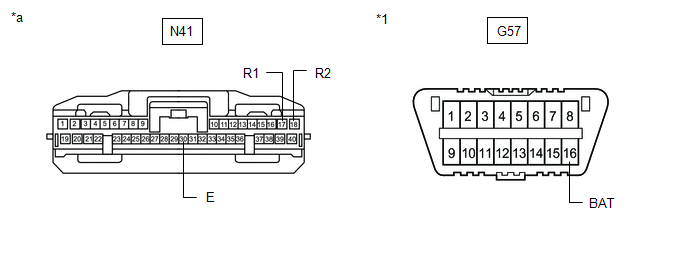
| *1 | DLC3 | - | - |
| *a | Front view of wire harness connector (to Clearance Warning ECU Assembly) | - | - |
Standard Resistance:
| Terminal No. (Symbol) | Wiring Color | Terminal Description | Condition | Specified Condition |
|---|---|---|---|---|
| N41-17 (R1) - N41-18 (R2) | L - W | HIGH-level CAN bus line - LOW-level CAN bus line | Cable disconnected from negative (-) auxiliary battery terminal | 54 to 69 Ω |
| N41-17 (R1) - N41-30 (E) | L - W-B | HIGH-level CAN bus line - Ground | Cable disconnected from negative (-) auxiliary battery terminal | 200 Ω or higher |
| N41-18 (R2) - N41-30 (E) | W - W-B | LOW-level CAN bus line - Ground | Cable disconnected from negative (-) auxiliary battery terminal | 200 Ω or higher |
| N41-17 (R1) - G57-16 (BAT) | L - R | HIGH-level CAN bus line - Auxiliary battery positive (+) | Cable disconnected from negative (-) auxiliary battery terminal | 6 kΩ or higher |
| N41-18 (R2) - G57-16 (BAT) | W - R | LOW-level CAN bus line - Auxiliary battery positive (+) | Cable disconnected from negative (-) auxiliary battery terminal | 6 kΩ or higher |
PARKING ASSIST ECU (w/ Panoramic View Monitor System)
Refer to Terminals of ECU.
Click here
(a) Disconnect the cable from the negative (-) auxiliary battery terminal.
(b) Disconnect the N44 parking assist ECU connector.
(c) Measure the resistance according to the value(s) in the table below.
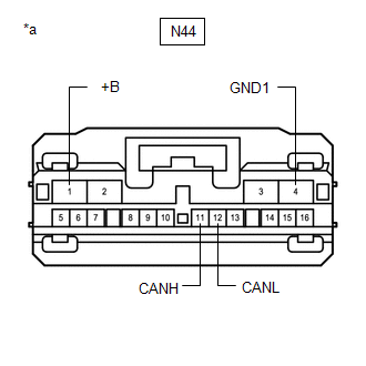
| *a | Front view of wire harness connector (to Parking Assist ECU) |
Standard Resistance:
| Terminal No. (Symbol) | Wiring Color | Terminal Description | Condition | Specified Condition |
|---|---|---|---|---|
| N44-11 (CANH) - N44-12 (CANL) | GR - W | HIGH-level CAN bus line - LOW-level CAN bus line | Cable disconnected from negative (-) auxiliary battery terminal | 54 to 69 Ω |
| N44-11 (CANH) - N44-4 (GND1) | GR - W-B | HIGH-level CAN bus line - Ground | Cable disconnected from negative (-) auxiliary battery terminal | 200 Ω or higher |
| N44-12 (CANL) - N44-4 (GND1) | W - W-B | LOW-level CAN bus line - Ground | Cable disconnected from negative (-) auxiliary battery terminal | 200 Ω or higher |
| N44-11 (CANH) - N44-1 (+B) | GR - R | HIGH-level CAN bus line - Auxiliary battery positive (+) | Cable disconnected from negative (-) auxiliary battery terminal | 6 kΩ or higher |
| N44-12 (CANL) - N44-1 (+B) | W - R | LOW-level CAN bus line - Auxiliary battery positive (+) | Cable disconnected from negative (-) auxiliary battery terminal | 6 kΩ or higher |
MULTIPLEX TILT AND TELESCOPIC ECU (w/ Power Tilt and Power Telescopic System)
Refer to Terminals of ECU.
Click here
(a) Disconnect the cable from the negative (-) auxiliary battery terminal.
(b) Disconnect the G63 multiplex tilt and telescopic ECU connector.
(c) Measure the resistance according to the value(s) in the table below.
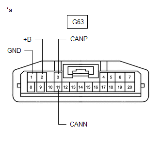
| *a | Front view of wire harness connector (to Multiplex Tilt and Telescopic ECU) |
Standard Resistance:
| Terminal No. (Symbol) | Wiring Color | Terminal Description | Condition | Specified Condition |
|---|---|---|---|---|
| G63-3 (CANP) - G63-11 (CANN) | R - W | HIGH-level CAN bus line - LOW-level CAN bus line | Cable disconnected from negative (-) auxiliary battery terminal | 54 to 69 Ω |
| G63-3 (CANP) - G63-1 (GND) | R - W-B | HIGH-level CAN bus line - Ground | Cable disconnected from negative (-) auxiliary battery terminal | 200 Ω or higher |
| G63-11 (CANN) - G63-1 (GND) | W - W-B | LOW-level CAN bus line - Ground | Cable disconnected from negative (-) auxiliary battery terminal | 200 Ω or higher |
| G63-3 (CANP) - G63-2 (+B) | R - B | HIGH-level CAN bus line - Auxiliary battery positive (+) | Cable disconnected from negative (-) auxiliary battery terminal | 6 kΩ or higher |
| G63-11 (CANN) - G63-2 (+B) | W - B | LOW-level CAN bus line - Auxiliary battery positive (+) | Cable disconnected from negative (-) auxiliary battery terminal | 6 kΩ or higher |
POSITION CONTROL ECU ASSEMBLY LH (w/ Seat Position Memory System)
Refer to Terminals of ECU.
Click here
(a) Disconnect the cable from the negative (-) auxiliary battery terminal.
(b) Disconnect the U46 and U48 position control ECU assembly LH connectors.
(c) Measure the resistance according to the value(s) in the table below.
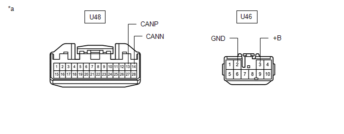
| *a | Front view of wire harness connector (to Position Control ECU Assembly LH) | - | - |
Standard Resistance:
| Terminal No. (Symbol) | Wiring Color | Terminal Description | Condition | Specified Condition |
|---|---|---|---|---|
| U48-13 (CANP) - U48-14 (CANN) | LG - R*1 L - W*2 | HIGH-level CAN bus line - LOW-level CAN bus line | Cable disconnected from negative (-) auxiliary battery terminal | 54 to 69 Ω |
| U48-13 (CANP) - U46-2 (GND) | LG - W-B*1 L - W-B*2 | HIGH-level CAN bus line - Ground | Cable disconnected from negative (-) auxiliary battery terminal | 200 Ω or higher |
| U48-14 (CANN) - U46-2 (GND) | R - W-B*1 W - W-B*2 | LOW-level CAN bus line - Ground | Cable disconnected from negative (-) auxiliary battery terminal | 200 Ω or higher |
| U48-13 (CANP) - U46-3 (+B) | LG - W*1 L - W*2 | HIGH-level CAN bus line - Auxiliary battery positive (+) | Cable disconnected from negative (-) auxiliary battery terminal | 6 kΩ or higher |
| U48-14 (CANN) - U46-3 (+B) | R - W*1 W - W*2 | LOW-level CAN bus line - Auxiliary battery positive (+) | Cable disconnected from negative (-) auxiliary battery terminal | 6 kΩ or higher |
- *1: for TMC Made
- *2: for TMMK Made
OUTER MIRROR CONTROL ECU ASSEMBLY LH (w/ Seat Position Memory System)
Refer to Terminals of ECU.
Click here
(a) Disconnect the cable from the negative (-) auxiliary battery terminal.
(b) Disconnect the J28 outer mirror control ECU assembly LH connector.
(c) Measure the resistance according to the value(s) in the table below.
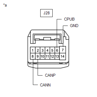
| *a | Front view of wire harness connector (to Outer Mirror Control ECU Assembly LH) |
Standard Resistance:
| Terminal No. (Symbol) | Wiring Color | Terminal Description | Condition | Specified Condition |
|---|---|---|---|---|
| J28-9 (CANP) - J28-8 (CANN) | P - W | HIGH-level CAN bus line - LOW-level CAN bus line | Cable disconnected from negative (-) auxiliary battery terminal | 54 to 69 Ω |
| J28-9 (CANP) - J28-7 (GND) | P - W-B | HIGH-level CAN bus line - Ground | Cable disconnected from negative (-) auxiliary battery terminal | 200 Ω or higher |
| J28-8 (CANN) - J28-7 (GND) | W - W-B | LOW-level CAN bus line - Ground | Cable disconnected from negative (-) auxiliary battery terminal | 200 Ω or higher |
| J28-9 (CANP) - J28-6 (CPUB) | P - LA-L | HIGH-level CAN bus line - Auxiliary battery positive (+) | Cable disconnected from negative (-) auxiliary battery terminal | 6 kΩ or higher |
| J28-8 (CANN) - J28-6 (CPUB) | W - LA-L | LOW-level CAN bus line - Auxiliary battery positive (+) | Cable disconnected from negative (-) auxiliary battery terminal | 6 kΩ or higher |
OUTER MIRROR CONTROL ECU ASSEMBLY RH (w/ Seat Position Memory System)
Refer to Terminals of ECU.
Click here
(a) Disconnect the cable from the negative (-) auxiliary battery terminal.
(b) Disconnect the J6 outer mirror control ECU assembly RH connector.
(c) Measure the resistance according to the value(s) in the table below.
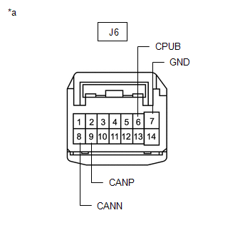
| *a | Front view of wire harness connector (to Outer Mirror Control ECU Assembly RH) |
Standard Resistance:
| Terminal No. (Symbol) | Wiring Color | Terminal Description | Condition | Specified Condition |
|---|---|---|---|---|
| J6-9 (CANP) - J6-8 (CANN) | P - W | HIGH-level CAN bus line - LOW-level CAN bus line | Cable disconnected from negative (-) auxiliary battery terminal | 54 to 69 Ω |
| J6-9 (CANP) - J6-7 (GND) | P - W-B | HIGH-level CAN bus line - Ground | Cable disconnected from negative (-) auxiliary battery terminal | 200 Ω or higher |
| J6-8 (CANN) - J6-7 (GND) | W - W-B | LOW-level CAN bus line - Ground | Cable disconnected from negative (-) auxiliary battery terminal | 200 Ω or higher |
| J6-9 (CANP) - J6-6 (CPUB) | P - LA-L | HIGH-level CAN bus line - Auxiliary battery positive (+) | Cable disconnected from negative (-) auxiliary battery terminal | 6 kΩ or higher |
| J6-8 (CANN) - J6-6 (CPUB) | W - LA-L | LOW-level CAN bus line - Auxiliary battery positive (+) | Cable disconnected from negative (-) auxiliary battery terminal | 6 kΩ or higher |
LUGGAGE CLOSER MOTOR ASSEMBLY (w/ Power Trunk Lid System)
Refer to Terminals of ECU.
Click here
(a) Disconnect the cable from the negative (-) auxiliary battery terminal.
(b) Disconnect the R7 luggage closer motor assembly connector.
(c) Measure the resistance according to the value(s) in the table below.
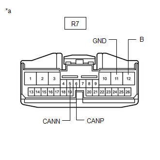
| *a | Front view of wire harness connector (to Luggage Closer Motor Assembly) |
Standard Resistance:
| Terminal No. (Symbol) | Wiring Color | Terminal Description | Condition | Specified Condition |
|---|---|---|---|---|
| R7-6 (CANP) - R7-5 (CANN) | P - W | HIGH-level CAN bus line - LOW-level CAN bus line | Cable disconnected from negative (-) auxiliary battery terminal | 54 to 69 Ω |
| R7-6 (CANP) - R7-11 (GND) | P - W-B | HIGH-level CAN bus line - Ground | Cable disconnected from negative (-) auxiliary battery terminal | 200 Ω or higher |
| R7-5 (CANN) - R7-11 (GND) | W - W-B | LOW-level CAN bus line - Ground | Cable disconnected from negative (-) auxiliary battery terminal | 200 Ω or higher |
| R7-6 (CANP) - R7-12 (B) | P - B | HIGH-level CAN bus line - Auxiliary battery positive (+) | Cable disconnected from negative (-) auxiliary battery terminal | 6 kΩ or higher |
| R7-5 (CANN) - R7-12 (B) | W - B | LOW-level CAN bus line - Auxiliary battery positive (+) | Cable disconnected from negative (-) auxiliary battery terminal | 6 kΩ or higher |
STEREO COMPONENT EQUALIZER ASSEMBLY
Refer to Terminals of ECU.
Click here
(a) Disconnect the cable from the negative (-) auxiliary battery terminal.
(b) Disconnect the G15 stereo component equalizer assembly connector.
(c) Measure the resistance according to the value(s) in the table below.
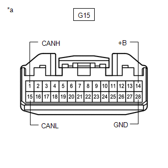
| *a | Front view of wire harness connector (to Stereo Component Equalizer Assembly) |
Standard Resistance:
| Terminal No. (Symbol) | Wiring Color | Terminal Description | Condition | Specified Condition |
|---|---|---|---|---|
| G15-1 (CANH) - G15-15 (CANL) | P - W | HIGH-level CAN bus line - LOW-level CAN bus line | Cable disconnected from negative (-) auxiliary battery terminal | 54 to 69 Ω |
| G15-1 (CANH) - G15-28 (GND) | P - LA | HIGH-level CAN bus line - Ground | Cable disconnected from negative (-) auxiliary battery terminal | 200 Ω or higher |
| G15-15 (CANL) - G15-28 (GND) | W - LA | LOW-level CAN bus line - Ground | Cable disconnected from negative (-) auxiliary battery terminal | 200 Ω or higher |
| G15-1 (CANH) - G15-14 (+B) | P - LA-R | HIGH-level CAN bus line - Auxiliary battery positive (+) | Cable disconnected from negative (-) auxiliary battery terminal | 6 kΩ or higher |
| G15-15 (CANL) - G15-14 (+B) | W - LA-R | LOW-level CAN bus line - Auxiliary battery positive (+) | Cable disconnected from negative (-) auxiliary battery terminal | 6 kΩ or higher |
VEHICLE APPROACHING SPEAKER CONTROLLER
Refer to Terminals of ECU.
Click here
(a) Disconnect the cable from the negative (-) auxiliary battery terminal.
(b) Disconnect the G42 vehicle approaching speaker controller connector.
(c) Measure the resistance according to the value(s) in the table below.
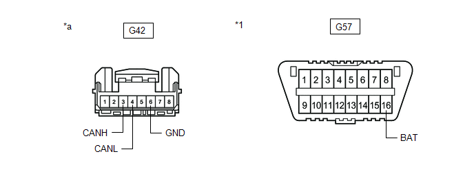
| *1 | DLC3 | - | - |
| *a | Front view of wire harness connector (to Vehicle Approaching Speaker Controller) | - | - |
Standard Resistance:
| Terminal No. (Symbol) | Wiring Color | Terminal Description | Condition | Specified Condition |
|---|---|---|---|---|
| G42-3 (CANH) - G42-4 (CANL) | B - W | HIGH-level CAN bus line - LOW-level CAN bus line | Cable disconnected from negative (-) auxiliary battery terminal | 54 to 69 Ω |
| G42-3 (CANH) - G42-6 (GND) | B - W-B | HIGH-level CAN bus line - Ground | Cable disconnected from negative (-) auxiliary battery terminal | 200 Ω or higher |
| G42-4 (CANL) - G42-6 (GND) | W - W-B | LOW-level CAN bus line - Ground | Cable disconnected from negative (-) auxiliary battery terminal | 200 Ω or higher |
| G42-3 (CANH) - G57-16 (BAT) | B - R | HIGH-level CAN bus line - Auxiliary battery positive (+) | Cable disconnected from negative (-) auxiliary battery terminal | 6 kΩ or higher |
| G42-4 (CANL) - G57-16 (BAT) | W - R | LOW-level CAN bus line - Auxiliary battery positive (+) | Cable disconnected from negative (-) auxiliary battery terminal | 6 kΩ or higher |
READ NEXT:
 Problem Symptoms Table
PROBLEM SYMPTOMS TABLE HINT:
Use the table below to help determine the cause of problem symptoms.
Inspect the fuses and relays related to this system before inspecting the suspected areas below.
How To Proceed With Troubleshooting
CAUTION / NOTICE / HINT PRECAUTIONS WHEN TROUBLESHOOTING NOTICE:
Because the order of diagnosis is important to allow correct diagnosis, make sure to begin troubleshooting using How to Proceed with
Utility
UTILITY INITIALIZE THE CONNECTION INFORMATION OF A GATEWAY FUNCTION EQUIPPED ECU (BUS MONITOR ECU) (a) Connect the Techstream to the DLC3. (b) Turn the power switch on (IG). (c) Turn the Techstream on
SEE MORE:
Test Mode Procedure
TEST MODE PROCEDURE TEST MODE PROCEDURE NOTICE: After replacing the absorber control ECU, it is necessary to perform registration of vehicle identification information. Vehicle identification information is automatically acquired when the system enters test mode. HINT:
When entering test mode, th
Hybrid/EV Battery State of Charge High (P0C3000)
DESCRIPTION The battery ECU assembly monitors the operation of the hybrid battery system and will store this DTC if it detects a malfunction. DTC No. Detection Item DTC Detection Condition Trouble Area MIL Warning Indicate P0C3000 Hybrid/EV Battery State of Charge High Even thou
